Scratch building a Midland 4-2-2 "Spinner"
Another locomotive is about to take to the rails on Halifax. This time it's a model of the Midland single driver 4-2-2 or "Spinner", as they were known. This model certainly wasn't in my original plans for Halifax but, having discovered that some of the early batch with 7'4" drivers were allocated to Leeds Holbeck in the early 1920s, I couldn't resist building one. Why the interest in the early batch? It's simply that I feel I can get away with using a pair of Alan Gibson's 7'0" drivers on this model. Given that the tyres on these locos would probably have been getting a bit thin by the time they were "cast off" to the West Riding I reckon that they were more like 7'3" or even 7'2".
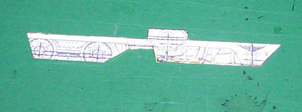
Anyway, construction started in my usual way with a photocopied drawing glued with PVA to a sheet of 15 thou brass. The axle holes were drilled out as accurately as possible using the drawing as a template. I'd decided to try and build the model as a rigid framed locomotive with all the axle holes in the main frames and with no bogies. The reason for this decision was to see if it is possible to prevent the problems caused by unrestricted bogie swing. The "Spinner" has footplate valences that cover the top part of the bogie wheels and I'm anxious to preserve this feature on the model. The success I'd had build my Compound with a rigid bogie frame suggests that something similar would be possible with the "Spinner" particularly since its wheelbase is shorter than the Compound.
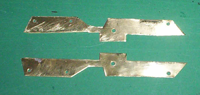
Once the initial holes were drilled I cut out the frame (yes, using my scissors again!) and after a little bit of straightening of the brass where it had curled tack soldered it to another piece. The holes were drilled through and then gradually opened up using drills and broaches until the correct size of axle holes were opened. The second frame was cut out using the first as a guide and then the two pieces were unsoldered.
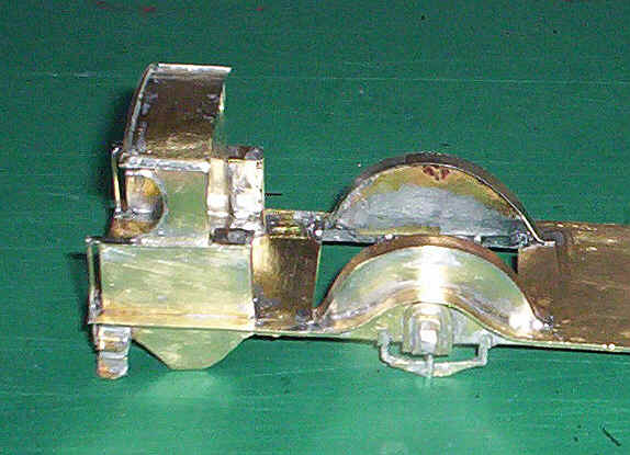
I decided I'd open out the rear trailing axle hole to about 1/8th inch diameter (to allow vertical and horizontal movement of this axle.) This proved ineffective in the end but the two larger axle holes for the driving and rear axle at least allowed me to use the Comet frame alignment jigs. Some spare frame spacers were soldered in place with two with holes in the correct place for the body securing bolts.
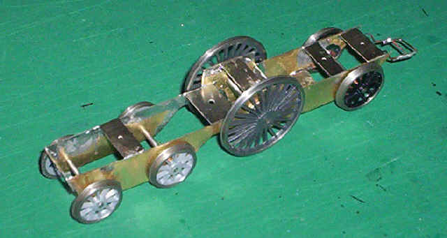
I next test fitted the wheels to see if the wheels were all touching the flat surface I use for building a chassis. Not surprisingly they weren't, so some adjustment of one of the "bogie" axle holes was necessary with a file. Then I soldered in place various additional frame spacers.
Testing the chassis on the layout was, initially, pretty disastrous (it usually is for me until I tweak things). The rear axle kept derailing so I tried the same method as on my 2-4-0; a brass tube over the axle with a springy pieces of brass wire pressing the axle down - no success.
Eventually I pulled of the rear wheels and soldered some washers in the right place as bearings. Obviously, there was a bit of fiddling needed here to get them in the right position! At least the wheels all touched the flat surface again. Testing showed no improvement in running so I removed the driving wheels and tested the chassis as a 4-0-2. It stayed on the track even at a scale 100mph.
After some thought, I decided that by opening the driving axle hole up at the top there'd be more play vertically. This time the loco chassis stayed on the track. I rigged up a temporary coupling to allow testing with the tender from one of my 4-4-0s and ran the chassis around the layout. There were still odd derailments and the odd short circuit when wheels touched the frames. This was cured easily by inserting washers behind the wheels; there is still enough side play on all the axles to negotiate 3'0" radius curves as I'd narrowed the frame at the front to allow the front "bogie" axle more side play.
Putting some weights on the chassis dramatically improved track holding, to the point where very high speed running is possible with no derailments. Not, of course, that this is how I normally operate my layout, but it's a good test of whether a loco will run securely in normal use.
So the basic chassis works. It is not a particularly good one by S Scale Society standards but it works and that's all that really matters. Of course there's no motor in the locomotive which makes construction a lot easier.
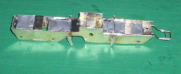
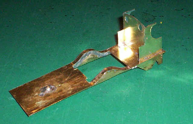
The brake gear was added next - spare etchings for the brake hangars and shoes and pieces of wire rod for the various linkages. A small strip of nickel silver was added between the two "bogie wheels" to represent the bogie frame. Next the chassis was weighted with small sheets of lead soldered in place ensuring that chassis would balance roughly about the centre axle. The frame structure was now much more rigid and, possibly because of this, I found that the tendency to derail occasionally had returned.
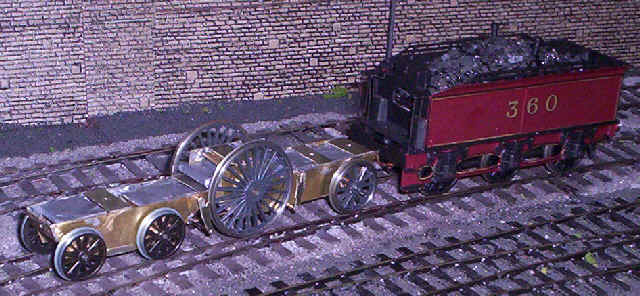
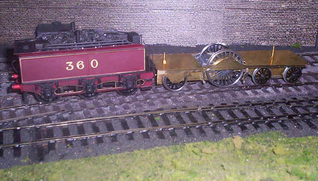
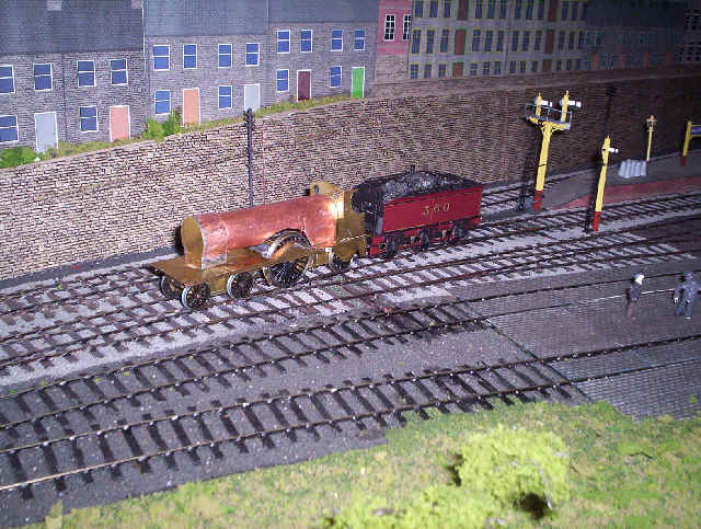
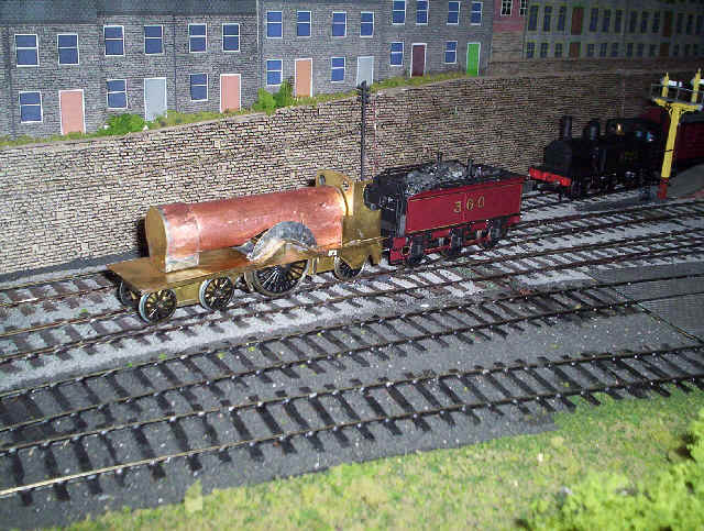
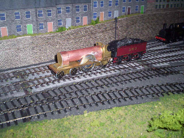
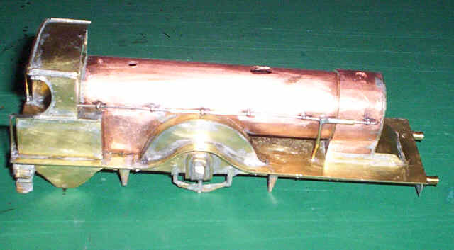
The final (?) solution seems to have been found; the front axle holes have been elongated slightly in a lateral direction, allowing the front axle to turn very slightly into the curve, the rear axle has had its side play reduced by adding some washers, whilst the rear "bogie axle" and driver are allowed about 1/8th inch side play. The driver remains free to rock vertically. The photo shows the rolling chassis coupled to the tender from one of my 4-4-0s which I use for testing purposes. Eventually, of course, the "Spinner" will have an identical tender built up from an Alan Gibson etch.
Once again I used the photocopies as a template for the valences to the footplate. They were cut out, straightened and filed to shape. The critical feature of the footplate and valence assembly will be that the valences will have to be far enough apart for the wheels not to touch. Measurement of the chassis and wheel side play suggest that this will need to be 30mm, which is precisely the figure shown on the diagram.
The footplate itself is almost certainly to be rather tricky as it curves up over the driving wheels.
To my surprise The footplate wasn't as difficult as expected. I constructed it out of two pieces; the front part extends from the front buffer beam to the rear of the curved valences. To allow clearance for the driving wheels it was necessary to cut a U shaped section out of this piece. The narrow strips produced as a result of this were gently curved to follow the valences and then the brass was soldered to one valence at a time. A smooth curve was formed over the valences and soldered in place a little section at a time.
Once both valences were in place - vertical and set in from the edge of the footplate at a sufficient distance from the wheels to allow side play of the wheels without touching the valences, it was time for the rear footplate. A rectangle of brass was cut and soldered in place butting tightly against the end of the curved section. A little solder and filing has ensured a virtually invisible joint. The footplate was then drilled to take the fixing bolts as seen in the photo above.
I was still a little unhappy about the track holding of the chassis with occasional and unpredictable derailments still occurring. I decided that unless I could overcome this problem there wasn't much point in proceeding. I have in my wheels box some Alan Gibson 4mm scale 8' 0" wheels intended for a Stirling single, which appear to have the "EM profile" tyres. As there is no discernible difference between the S Scale 7' 0" drivers and the 4mm 8' 0" in terms of diameter I decided to substitute the latter. In addition I elongated the driving wheel axle hole so that it is really just a slot about 3/16" long. I also replaced the rear trailing wheel with a tender wheel again with EM profile wheels. The transformation was dramatic. I've found it impossible to derail the chassis except on the sharp curve to the new goods yard and as that's 3' 0" radius this isn't surprising.
The eagle eyed will have spotted that the driver still has its crank pin boss. This will be hidden behind the outside springing which is such a feature of these early "Spinners".
Moving on to the next stage of construction the two cab sides were cut out together using a piercing saw for the curved cab cutouts and scissors for the straight cuts. The cab front was made in the same way as for the 1F 0-6-0T. The sides and front were then soldered to the footplate.
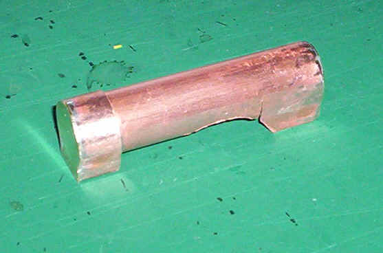
The boiler, smoke box and firebox unit follows a similar method of construction to the method used on the 2-4-0 with some modifications in the light of experience to make assembly easier.
Cut boiler and smoke box tubes tubes to length
Mark position for the vertical cuts for the front of the firebox and cut - this comes up roughly to the diameter line of the tube.
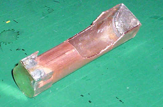
Make a lengthwise cut along the bottom of the "firebox section of the tube. This cut must be exactly half way between the top ends of the vertical cuts so that, when the firebox sides are bent straight they will be the same length. To my amazement, on this loco the straightened firebox sides are exactly the right length so that the fire box sits at the correct height on the footplate. Amazing!!
The really brutal part of construction started now with the removal of the lower part of the boiler to allow the drivers, with their excessive side play sufficient clearance. This was achieved using piercing and hack saws and Xuron snips. The rough edges were filed smooth.
Cut lengthwise along the smoke box tube.
I'd decided that I was going to bend the smoke box tube to produce the sides of the smoke box saddle. It would be easier and neater than soldering on tiny pieces of brass. I bent the ends near the lengthwise cut approximately 5mm from the cut and straightened them so that they were vertical when slid over the boiler tube.
I tinned the smoke box end and soldered a piece of brass sheet on the end so that I can bolt the boiler unit to the cab. Lots of heavy cleaning up with snips and files were necessary to produce a neat finish.
The smoke box was aligned so that the boiler unit sat square on both the fire box sides and the sides of the smoke box saddle. When this was satisfactory I tinned the front ends of both the boiler and smoke box tubes and then soldered a piece of brass sheet to form the front of the smoke box and smoke box saddle. This piece needs to be cut to the correct vertical height so as to allow the entire boiler so sit level so it extends about a millimetre below the sides of the smoke box saddle.
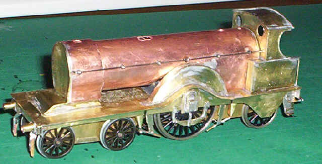
The boiler unit seen from above and below
The first photo of the main components of the locomotive suggest that the models will eventually look like a "Spinner". The boiler unit is now fixed semi permanently to the footplate and cab. A piece of brass was soldered under the smoke box saddle to form a front mounting point. Holes were drilled through the front of the cab and the rear of the firebox as well as through the footplate and the underside of the smoke box saddle. A bolt fixed the firebox to the cab and a self tapping screw attached the smoke box end. Some adjustments to the cut outs on the underside of the boiler were found necessary to give sufficient clearance for the drivers.
Moving on the next stage was the construction of the splashers. In the photo below the front face of the splasher has been cut from brass and soldered in place.
This photo shows several stages further on.
The splashers have been completed by adding the curved tops
The small slits at the front of the fire box have been filled with solder and filed smooth.
The smoke box saddle base and the "piano lid" front have been fabricated from brass.
The supports for the cantilevered springs have been bent from 1mm square brass section and soldered behind the footplate valance.
At this stage the boiler unit is not screwed and bolted in place so there are some gaps showing.
The photo below summarises a lot of work.
The cab roof added with brass wire along edges for rain strip, filed flat on the top to give impression of metal strips.
The tops and sides of the rectangular lower part of the cab sides added.
The beading around the cab cut outs and that really awkward beading across the whole width of the cab were added from nickel silver strip sweated in place.
The cab handrails were added - I wanted a firm finish so the top of the handrail is bent at 90 degrees and soldered to the inside of the cab rather than to the beading.
How to represent the cantilevered springs and axle boxes puzzled me at first. In the end the solution was simple.
A piece of square section brass was bent into a U shaped and soldered behind the footplate valance.
I cut a piece of brass to a "spring shape" and soldered this to the lower part of the "U".
Various bits of brass and nickel silver were cut to size and soldered in place to represent the various parts of the spring hangers.
The driving wheel axle boxes were soldered one layer at a time from four pieces of brass to give the chunky feel of the original. The last piece was bent over at the top to give the impression of what I imagine if the lubricating access lid.
It's all very impressionistic but gives the effect I want for my models.
With this stage of construction complete the boiler unit was permanently bolted to the running plate. I've accepted that the area under the boiler is going to be solid, as the chassis is completely full of lead at this point. Thus, there's going to be no chance I can replicate the slide bars and valve gear between the frames.
The minute gaps between the smoke box saddle and the running plate have been filled with epoxy resin, as has the gap between the firebox and the cab front. Some time was then spent opening up the holes for the boiler fittings, definitely not a favourite task of mine.
Holes were drilled for the handrail knobs (donated from an old Airfix Royal Scot) and these were super-glued in place together with the handrail wires.
On the right hand side of the smoke box the various bits of pipe work for the ejector were made up from brass tube, nuts and brass wire threaded over the handrail wire as in the photo below.
Viewed from the other side, the sandbox arrangements can be seen, as well as the prominent guard irons at the front. These latter caused a lot of head scratching as there is precious little space between the front of the bogie wheels and the buffer beam. However, there was just enough room to squeeze them in; they are simply a strip of brass, cut and filed to shape and soldered to the front of the side frames.
For once the Midland Railway made live easy for the modeller when designing the sandboxes. They were butted up against the running plate valances. I used very thin 5 thou brass sheet folded to give the appearance of a hefty triangular prism. First a triangle was marked on the brass and then using pliers I simply bent the sheet back at right angles to form a U shaped channel which tapers almost to a point at the base of the sandbox. This channel was then filled with solder to strengthen it and soldered to the rear of the valance. The pipes carrying the sand to the railhead were bent to the correct profile butted up against the base of the sandboxes and soldered to the brake hanger cross wires. When the chassis is screwed back to the body the gap is invisible. A further strengthening crosswire was soldered to the pipes and frame so that they are held firmly in place.
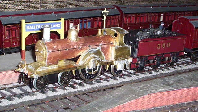
My favourite part of construction has now been reached, the detailing which brings the model to life. The chimney, smoke box door, dome with attached Salter valves, vacuum brake pipe, handrails and trailing axle axle boxes and springs are now in place together with the lamp irons. The safety valve cover is a temporarily in place just for the photo.
As can be seen the chassis has now been painted and, to my great pleasure, the loco runs beautifully.
The new tender for the "Spinner" is now completed using my usual format of an Airfix "Royal Scot" tender drive unit re-wheeled to S Scale. The locomotive itself is now complete with self-adhesive tape in place for the boiler bands.
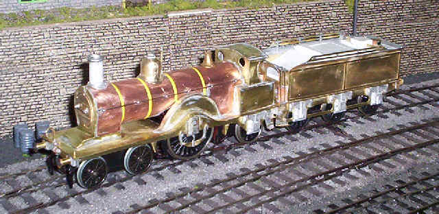
The primer undercoat has gone on and the loco is ready for the Derby paint shop and the application of "Midland Red"
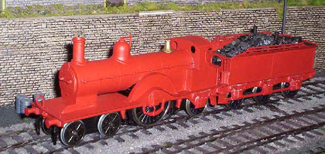
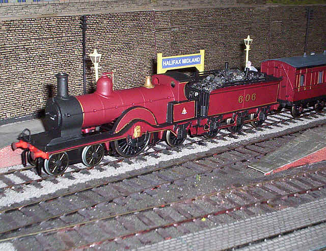
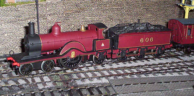
The completed model is shown below in two images