Building a BR 515 battery multiple unit
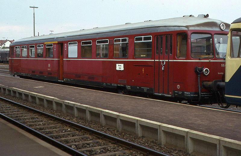
A BR 515 at Siershahn in August 1983.
515.509 – 580, 604 – 638, 652 – 661
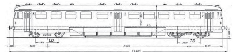
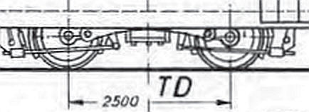
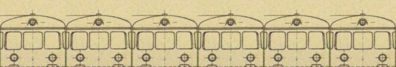
The first requirement for an accurate model is a diagram. An old edition of an Eisenbahn Journal Special issue "Akku Triebwagen" produced one. The BR 515s came in several versions but the one I'm going to model includes a small first class compartment.
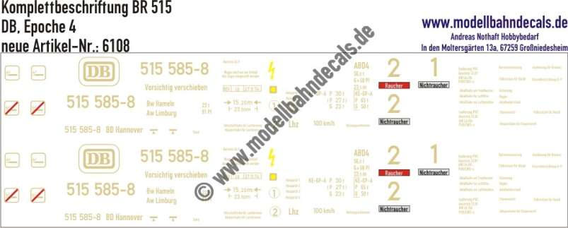
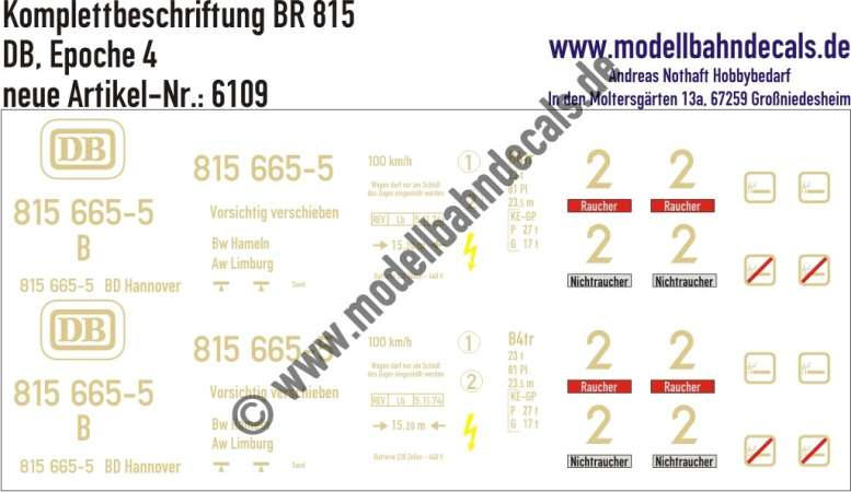
Looking ahead to the final stage of construction Modellbahn Decals produce complete sets of lettering for both the BR515 and the similar unpowered trailer BR815.
The number 515 585-8 is actually for the version with a large first class section so I probably request a number change when I order them.
Construction starts with the purchase and modification of another tramcar bogie from the former BEC range. The version I've chosen is a 38mm wheelbase with a single powered bogie and a dummy unpowered bogie.
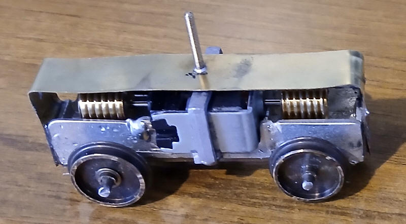
The powered bogie has been supplied with the correct size of disc wheel on O gauge axles. The wheels were moved along the axles to the correct position for S Scale. The axles have been shortened so that the axles extend about 3mm beyond the face of the wheels.
The bogie comes without any pivot position so I've arrange this by bending a strip of brass into an inverted U shape. A bolt has been inserted into a hole over the centre of the bogie and the brass glued to the bogie frame with epoxy resin. This will not be very strong but the next stage will overcome that.
 |
 |
The bogies were relatively lightweight and also largely hidden behind the skirt of the body. The model bogie is from a O Scale brass model. As usual I have decided to build a basic frame side and add detail from card later on when I see how much clearance is needed for the bogies to rotate when the body is complete.
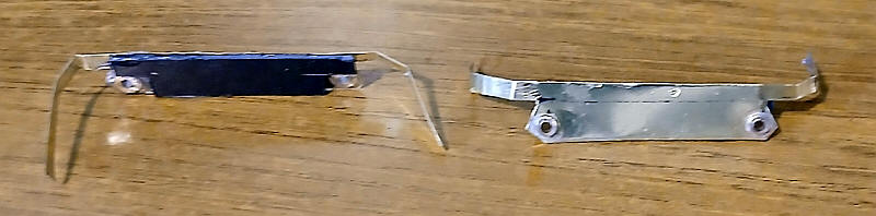
The frame sides were cut from thin brass as in the image above. The position of the axles was marked exactly on the brass and the holes opened up with broaches until 1/16th inch diameter inside axle bearings could be soldered in place. These will fit over the extended ends of the axles. The brass sheet was cut so as to give a solid centre section with strips at either end about 3mm wide which are bent and soldered to the brass pivot bar on the bogies

The power bogie in its raw state.
The unpowered bogie is similar to the powered one but for a pivot point I drilled a hole through the base of the bogie frame and then used layers of mounting board to build a base for the brass sheet that forms a rubbing plate when attached to the vehicle's frame.
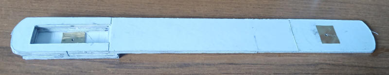
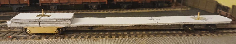
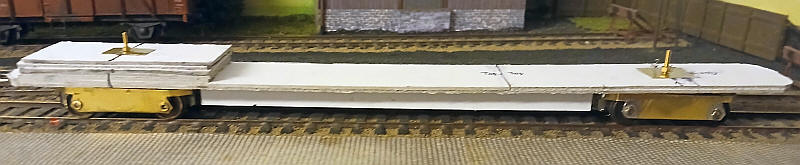
The frame of the model is built from multiple layers of mounting board overlapped for strength.
The two photos below show the frame looking from above (top photo) and below (bottom photo)

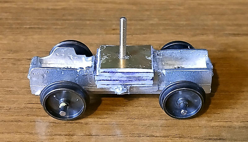
Whilst the unpowered bogie will allow the model's floor to be at the correct height the powered bogie is obviously higher so I have cut a hole in the base of the frame and built up layers of card around it onto which is glued another layer of card to act as the pivot point. I've used thin sheets of brass on both sides of the frame to form a rubbing plate and also a firm base for securing the pivot bolts of the bogies.
The bogies have been loosely attached to the frame and initial test running was problem free although obviously this will be better when the unpowered bogie has pick up wires attached.
The side frames for the unpowered bogie have been added in a similar way to the powered bogie except that the end pieces have been soldered directly on to the cast metal of the bogie. On the real vehicle the batteries were attached under the floor. I've strengthened the floor by gluing some long strips of mounting board to the underside.
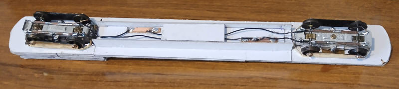
The two bogies have been linked together with wires - to ease future maintenance some copper clad strips have been glued in between the strengthening strips so that each bogie can be unsoldered without disturbing the other or unsoldering the wires on the bogies.
Running is delightfully smooth and quiet.
Detailing of the bogie frames will take place once the body has been completed.
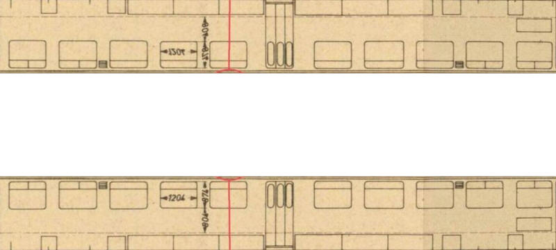
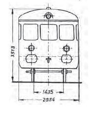
The first stage of constructing the body is to make a net of the two centre sections of the body and the blank section for the roof. This centre section had been calculated from the end drawing of the vehicle.

On the real BR515 the sides and roof have no real join so the best solution is to very carefully bend the initial curve of the roof with a small diameter piece of wood (a garden cane) held inside the body and a steel ruler presses against the card to make a sharp bend but at the same time ensuring that the narrow strip above the window stays vertical with the body sides.
The outer layer is seen here with the window openings cut very slightly over size, probably by about half a millimetre along each edge. Some superglue has been run along the inside of the card above the window and also on the sharp curve of the roof. This adds considerable strength to this delicate area.
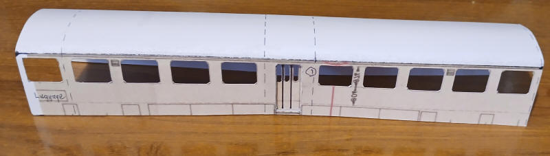
The recessed centre door is now in place made by cutting out the door opening and adding a packing piece of card behind the opening and then the door was glued in place.
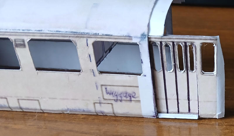
These two images show how I created one of the distinctive features of the BR515s, the alight curvature at the bottom of the body side,
15mm wide strips of mounting card were chamfered along the bottom edge. Then a line was drawn on the inside of the body sides about 5mm from the bottom. Using two steel rulers the lower bodyside was bent inwards slightly. The mounting board was then glued to the body as seen in the lower image.
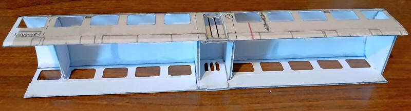
Finally, the four interior cross sections were glued in place. These were made by gluing the thin card printout onto mounting card and the carefully cut out around the outline.
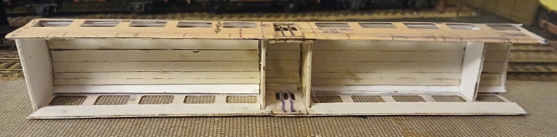
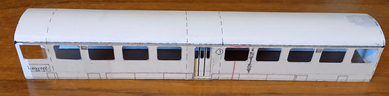
The roof has been strengthened by adding multiple layers of card inside the body shell. Two layers of card were cut and curved to fit in the different sections of the body and secured with epoxy resin. Finally narrow strips of greyboard cut and glued inside the body shell roof. This gives a really strong structure.
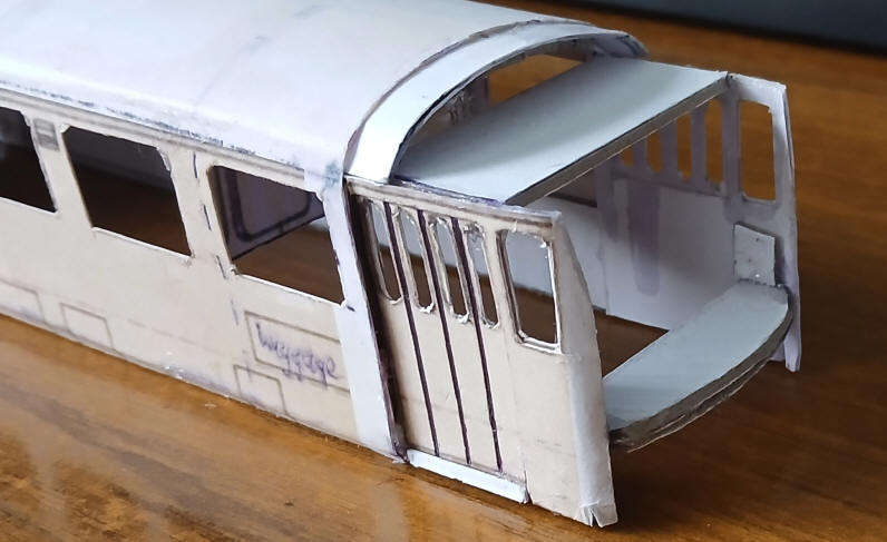
The next stage is likely to prove the most difficult part of construction - the cab ends and roof are a complex mix of thin parts and curves in multiple directions.
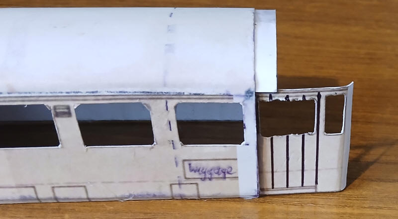
The photo above is the foundation of the leading doors which at Gepackabteil end (luggage area) have four parts.
A second layer with the windows cut out correctly is stuck to the foundation layer.

A final layer is cut out for the top layer.
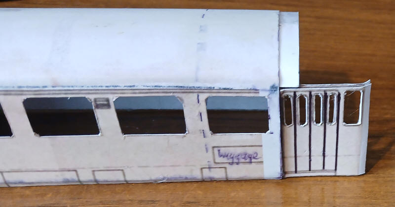
Finally, this added to the sides and a piece for the door sill added from mounting board. The lower edge has been bent to produce the curved lower edge of the body.
Two layers of mounting board have been added at the front of the cab sides to give a secure foundation for the lower cab front and also to act as one of the locations for the bolts which will secure the body to the chassis.

The body placed on the chassis.
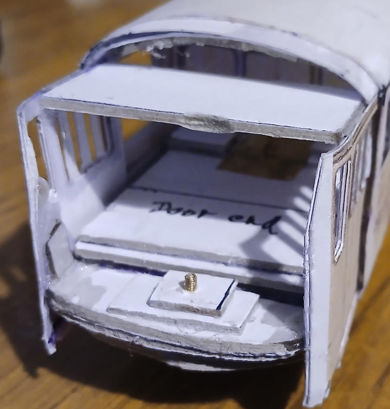
The method of securing the body to the chassis involves drilling a hole through the base of the chassis and the curved part of the body end. A 10BA nut is trapped with a piece of mounting board with a square cut in it. The nut is the trapped within the square by gluing another piece of card on top.
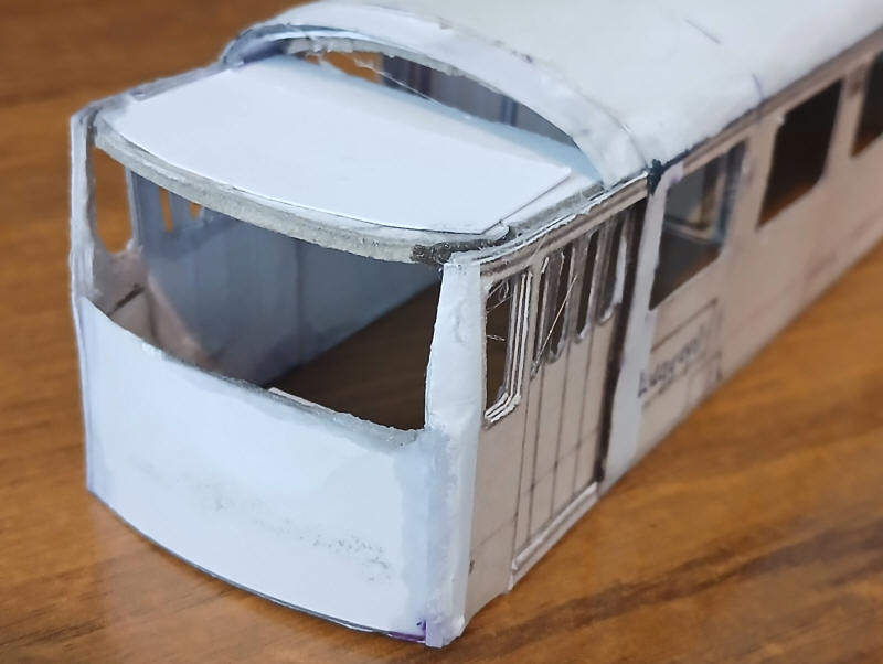
I've now added the first layer of the lower half of the cab front out of thin card. The ends have been tucked in between the layers of the cab sides where they curve around. I've used superglue to hold the card in place. At the top of the cab a layer of mounting board has been secured in place with the front edge about 5mm further back than the lower half of the cab front.
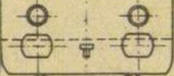
The cab front is probably the hardest part of the construction. The print out for the cab was split into two and the windows were cut out. The top half of the cab was glued onto curved sides and also to the mounting board above the windows. Then the lower part of the cab front had holes cut for the recessed buffers and coupling hook and glued in place. The ends were trimmed to match the cab sides.
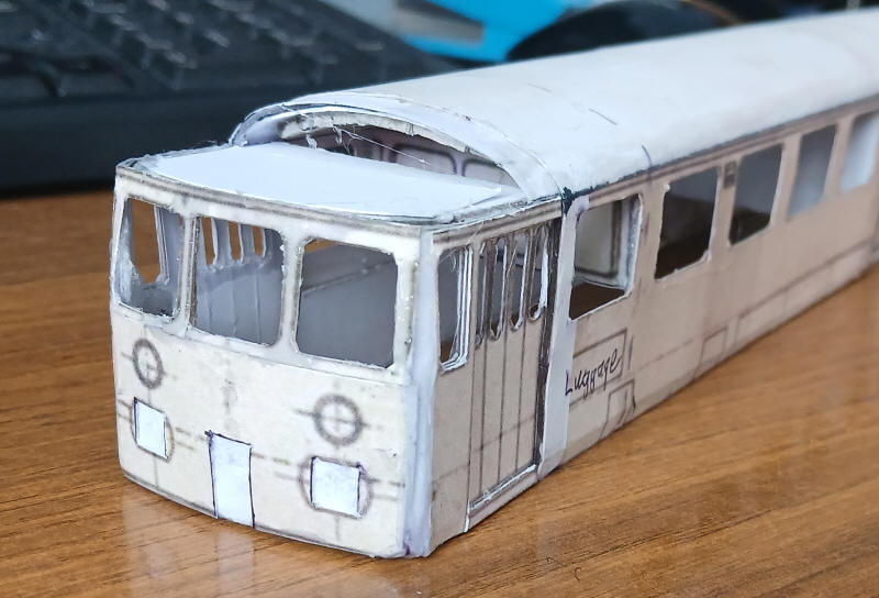
The window frames are extremely fragile so strips of nickel silver were secured behind the two central frames using superglue reinforced with epoxy.
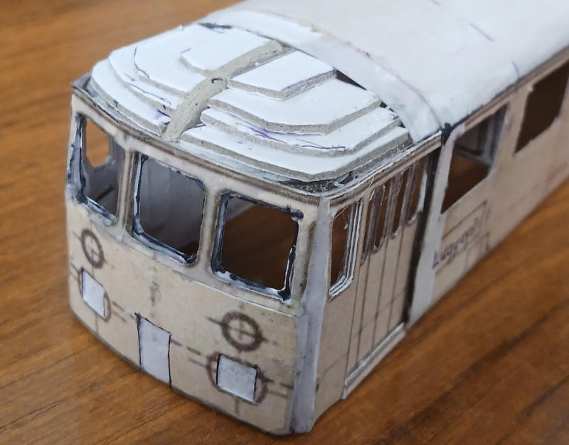
I've now added the layers for the substructure of the dome at the end of model. The piece of greyboard in the centre is the longitudinal profile board.
I've also added what will become the black rubber sealing strip around the glass in the cab windows, This is an extremely delicate tracery of card secured in place with superglue.

To make the domed end I've used a print out from the BR798 I built some years ago. This is printed out on paper and trimmed to produce a very strange shape which can be formed into the required shape.

The whole of the dome end sub-structure and the underside of the paper were coated in epoxy resin and then the paper was manipulated as the epoxy began to set. It is a messy job but within about ten minutes it has formed a hard and smooth surface. Some additional epoxy will be smeared over the surface later to smooth out an irregularities.
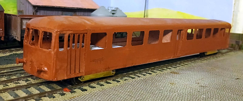
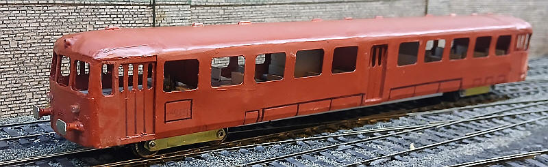
In this view both ends have been completed using a mixture of epoxy and milliput to give the dome ends. I've also fixed the buffers in place. I decided to spray the body so as to assist in smoothing out the dome ends. I have also removed the card inside the windows that were intended to represent to rubber seals around the glass, as they altered to proportions of the windows significantly making them appear much smaller.
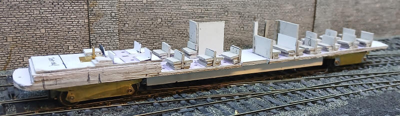
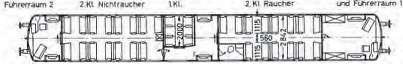
The interior has now been added using multiple layers of greyboard to form the seats. On the BR 515 these were very basic bench type seats in second class whilst first class passengers had a six seater compartment with much better seating. There is also a toilet compartment.
The large metal buffer heads have been cut from nickel silver strip and glued with both superglue and epoxy to the cast metal buffers. Rain strips from microstrip, headlights from lengths of plastic tube have also been added. The various access doors for the batteries and charging points are simply indentations made from scoring the card with a biro to create a depression.