Building a DB BR55 0-8-0
55.1666 stands in the yard at Finnentrop on 12/4/46. This is one of the earlier BR55s which were slightly different in appearance to the model I am intending to build. Photo by G.E.Rabone
Some time ago I started to construct a model of a DB BR94 0-10-0 shunting tank locomotive. For various reasons, mainly because the chassis continually derailed on my sharp curves, I decided to abandon the project. However, this left me with a set of Scalelink driving wheels. The problem with the 0-10-0T was largely because of the length of the wheelbase.
Another possible model was the BR55 0-8-0 tender locomotive.
These had a wheelbase slightly shorter than the BR86 2-8-2T that successfully runs on my layout. Perhaps the BR55 would.
These were former Prussian railways locomotives with an incredible 5,155 being built between 1913 and 1921.
The diagram below comes from a long out of print book about the locomotive type. Some of the BR55s were still in use on my early visits to Germany, the last being withdrawn at the end of 1972
As I was out of stock of the thickness of brass sheet I use for chassis I decided to reuse the chassis from the aborted BR 94. This meant plug the original axle holes with solder but as I was unsure whether I could get the chassis to work properly I wasn't inclined to spend unnecessary cash and would accept the extra work involved.
Construction follows the same method used for my other German locomotives.
A drawing resized to S Scale is glued to the brass sheet. A sharp compass point is pressed through the axle centre mark on the diagram to mark the drilling points on the brass. The holes are then drilled using a very small diameter drill. The two sheets of brass to form the side frames are then tack soldered together and the holes are drilled through the second frame. Once this has been done I separate the two side frames and progressively enlarge the holes using drills and then broaches to enable 1/8 inch diameter top hat bearings to be inserted.
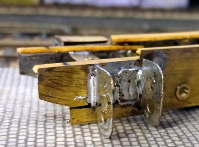
The frame sides are very flexible at this stage so I then solder strips of copperclad sleeper strips along the top edges of the frames and also soldered lengths of nickel silver along the bottom edge just below the axle holes.
The frames are then assembled with nickel silver frame spacers taken from spare Alan Gibson etchings. The frames are held in alignment using some old London Road alignment bolts and spacers.
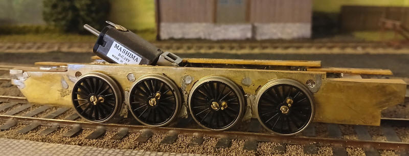
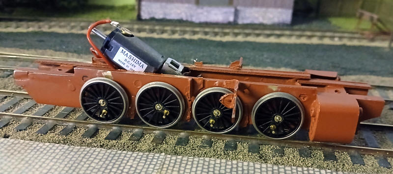
I've now soldered representations of the brake hangers and brake blocks directly to the frames rather than my usual method of hanging them on crosswires - these won't be in alignment to the wheels but will give the impression when viewed on the layout.
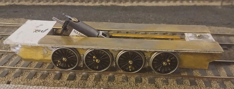
The photo shows the motor and wheels temporarily in place.
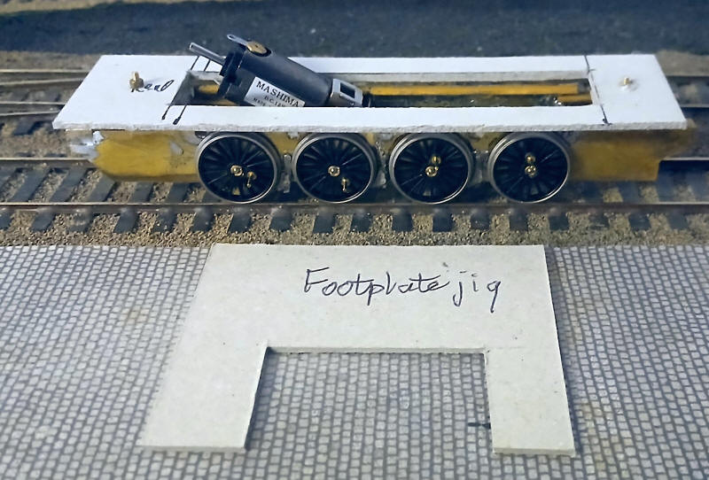
Before I move on to try to make a working chassis I've decided to make the footplate on to which the boiler and cab will be added. The basis of this is a piece of 2mm thick greyboard with a slot cut in the middle to accommodate the motor and to allow a view under the boiler. The footplate has blocks of card underneath the ends which sit on the frames. The footplate height jig can be seen - this ensures that the footplate is at the correct height relative to the rail head.
I've now added strips of brass for the footplate. These will make the card base much more rigid. Bolts have been secured through the holes in the card and these pass through the holes in the frame spacers at the front and rear of the chassis.
 |
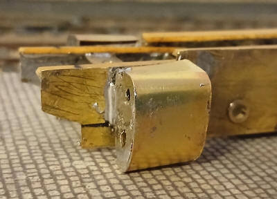 |
The next step was to add the cylinders. Rather than cutting metal from sheet I used part of the nickel silver etching from an Alan Gibson LMS 'Crab' 2-6-0 kit. The etchings comprises a fairly complex etch with the front and rear faces of the cylinder linked together with a chassis spacer. By cutting these into separate pieces for the front and rear of each cylinder and bending part of the frame spacer at right angles to form a tab four near perfect sized parts were obtained.
The exact position was marked out bearing in mind that the main piston rod on the BR55 loco is exactly in line with the axle centres. Once the front and rear cylinder faces were soldered to the main frames a piece of thin brass sheet was cut to size and soldered on to the edges of the cylinder faces.
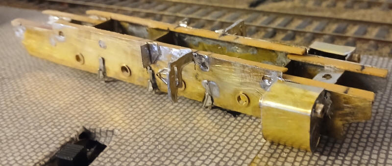
The motion brackets have now been added. The front brackets have been made out of the nickel silver etches from a Alan Gibson Stanier 2-6-4T which are incredibly similar to those found on the BR55. Each bracket is fabricated from four parts soldered together and then the end nearest the frame is bent at right angles and soldered to the frame . The rear bracket is a simple rectangle folded into an L shape and soldered to the frame 20mm to the rear of the main motion support bracket.
Some wagon top hat bearings have been soldered to the holes in the cylinders to act as either the guides for the piston rod or to represent other parts of the cylinders.
The frames are now ready to be painted in a reddy brown primer.
The wheels have now been secured in what I hope will be their final fitting. The motor has been wired up to the pick up strips on the underside of the chassis.
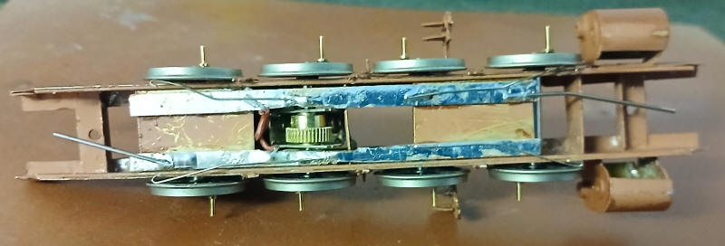
These are simply lengths of copper clad sleeper strip which have been glued to the two large horizontal frame spacer strips.
In a departure from what I have done for previous locomotives I have already added some pickup wires on the leading and rear driving wheels. In addition I have soldered two lengths of nickel silver wire to the copper clad strips , one at each end. These will allow easy testing of the loco by clipping the crocodile clips of the jumper leads I use for electrical testing.
A big problem
Having got this far the next step was to attach the coupling rods whcih I had already assembled using a simple jig as described in the sections about other DB steam locos. I test fitted the rods holding them in place with short lengths of the plastic insulation sleeves from ordinary domestic 3 core wire. The model ran smoothly. Then I started to solder the washers in place over the crankpins and it was immediately obvious that the melting point of the plastic that Scalelink use is considerably lower than Alan Gibsons' wheels. Despite taking great care two of the crankpins move their alignment and the model no longer ran smoothly.
Rather than give up on the project I managed to obtain some similar old Ronford wheels on Ebay and after removing the wheels and rods I reassembled the chassis as seen below.
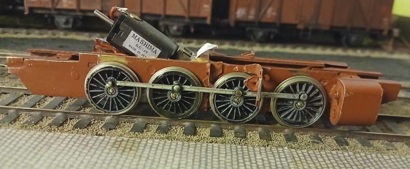
The building of the valve gear is the next step but I will wait until I am properly motivated to continue!