Scratch building a Johnson 0-6-0T
As a change from building a rake of three suburban coaches I've decided to construct another locomotive. Halifax Midland obviously needs a station pilot, now that there are four platforms and passenger trains coming and going all the time. The obvious candidate is one of the Johnson 0-6-0Ts. I've long held a fascination with these small locomotives, particularly with the "half cab" version, with their somewhat spartan cab arrangements. This probably dates from 1960 when, as an eight year old, I saw 41702 on a parcels train at Guide Bridge. 41702 spent its last six years, until withdrawal in 1962, at Gorton after the old Midland shed at Belle Vue closed inn 1956.
Further sightings of half cabs came in 1966 when I saw the former Staveley Iron Works locomotives, including the preserved 41708, stored at Rotherham in November. It was in the company of 41734, 41763, 41804, 41835 and two of the MR 0-4-0Ts 41528 and 41533.
However, upon detailed investigation it became apparent that very few of the "half cabs" were fitted with vacuum brakes, almost a pre-requisite for a station pilot. So it was with some regret that I decided that it would have to be one of the "full cab" locomotives, probably one of the two batches built to operate on the Keighley to Oxenhope branch. When displaced by 0-4-4Ts from their passenger duties several of these 0-6-0Ts migrated just down the line to Bradford Manningham and Leeds Holbeck. Photographic evidence shows they were used at Bradford Forster Square. I reckon that it's perfectly reasonable to suppose that one might have ended up at Halifax shed. Since I used to live in Keighley I feel it quite apt to have a model of one of these lcoomotives.
The Model
Construction started, as usual for me, with the chassis. Diagrams of the original were found in a series of articles in the 1975 issues of "Model Railways" magazine, as well as in "An illustrated Review of Midland Locomotives Volume 3" by Essery and Jenkinson. The diagrams were rescaled on my photocopier to full size for S Scale. A simplified outline of the frames was included in the "Model Railways" article so this was used as a template stuck to a sheet of .015" brass. This time I decided to cut out the frames using a jewellers' piercing saw thus avoiding the problems of curling of the brass when I used scissors!
The template had the axle centres parked on so I marked the point with a sharp point and drilled a small hole for each axle centre. After cutting out the first frame side I tack soldered this to the brass sheet, ensuring the straight top edges were aligned. Then I drilled the axle holes for the second frame using the previously drilled holes as a guide. These holes were then progressively opened out until about 1/16th inch.
Keeping the frames soldered together I used the first frame side as a template to cut out the second one. Any inaccuracies were remedied using needle files until the profiles on both were the same. Once satisfied the two pieces of brass were unsoldered and cleaned. The six axle holes were then opened up to take top hat bearings using broaches. Test fitting of the two frames over three bearings proved that the holes are all in exact alignment.
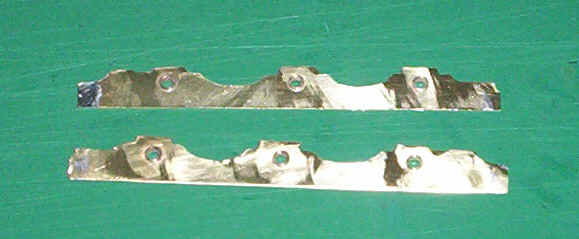
The photo below shows the two frames after the bearings had been soldered in place.
Rather than illustrate the construction in as much detail as my other locomotives I intend only to illustrate significant stages. All my techniques have been recorded on the other pages about locomotive construction so I don't want to become a repetitive bore!
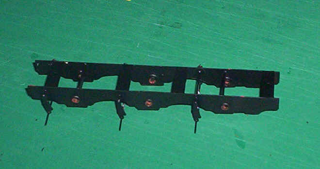
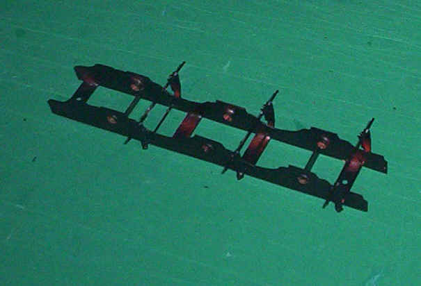
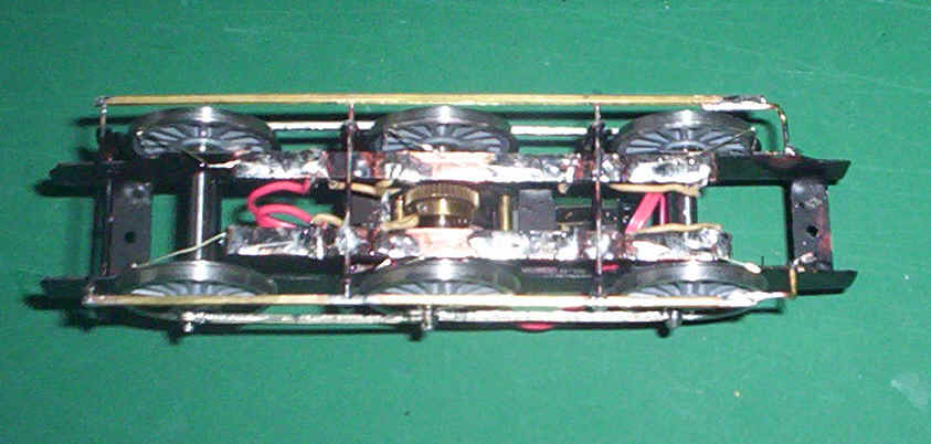
The two photos above show the assembled and painted frames. Four horizontal spacers, two placed at an acute angle near the outer bearings, and the wires for the top of the brake hangers produce a very rigid frame. Before painting, the wheels were trial fitted to ensure that the chassis sat four square. I then fitted the brake hangers (spares from my "Alan Gibson" etchings box) and then soldered the wires at the bottom of the brake hangers. These were cut over length so that the brake pull rods, which are outside of the wheels could be soldered in place once the locomotive chassis was running properly.
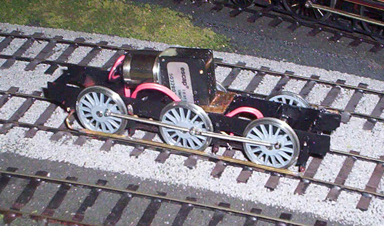
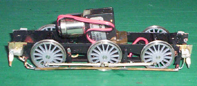
Moving on considerably, the photo above shows the chassis is now complete; it also runs beautifully smoothly, which is a necessity for a station pilot. The 4'7" drivers are by Alan Gibson moulded, unfortunately, in a light grey plastic. The plastic centres were removed from the tyres and superglued back in place in the hope that the tyres won't work loose. The crankpins were screwed in place and secured behind with a spot of Araldite.
The next step was to make the coupling rods using Alan Gibson's 4mm scale universal rods, an absolute boon as far as I'm concerned. My method for getting the lengths of the coupling rods aligned with the axles involves the use of London Road coupling rod alignment jigs. The three jigs were placed in the axle holes and the chassis tipped on its side. The three points were then pressed into a piece of paper stuck to a piece of chipboard. The points make pilot holes and three fine moulding pins were tapped into the wood at these precise points. It's a crude but effective jig, which I've used several times before. The coupling rod holes were opened up just enough to be a tight fit over the pins.
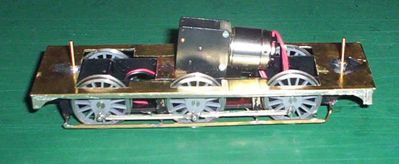
I have decided to use a Portescap RG4 with the short motor, which will fit nicely in the firebox. The wheels, together with the motor and gears, were put into the frames and were quartered using a Bill Bedford etched quartering jig. I have to admit to having had a great deal of trouble getting this quartering right. I suspect the accuracy is compromised by using a jig intended for 4mm and adapted to S Scale, as well as the inevitable inaccuracies in my construction of the chassis and rods. Needless to say, when I fitted the rods, the chassis did not roll smoothly. Considerably fiddling was necessary to get it right but in the end success was achieved.
To prevent the motor moving about when under power, I'd placed one of the frame spacers in the correct place to prevent backwards movement. A U shaped piece of brass sheet was soldered to the frame spacer immediately in front of the gearbox. This prevents both forwards and sideways movement; it can be seen unpainted in the photo above.
Once I was satisfied that the chassis was rolling smoothly I tightened the grub screw on the main gear and connected the motor wires to the track using leads. The loco ran smoothly so I fitted the nickel silver pickup wires to the PCB strips soldered under the chassis and spent some time testing the loco around the layout. The PCB strips aren't, perhaps the best solution to the pick up mounting problem. They are visible on all my locos if you look from the side but once in use I'm completely unaware of them as they're in the shadows under the loco. They do allow very easy access for cleaning and adjustments so I'll tolerate them.
Finally, the brake pull rods, made from square section brass, were soldered in place at the ends of the lower brake hanger wires. These can be seen, unpainted in the photos.
I must admit a feeling of real pride in completing this chassis, as it's the first one that I've completely built from scratch apart, of course, from the wheels and coupling rods!!!
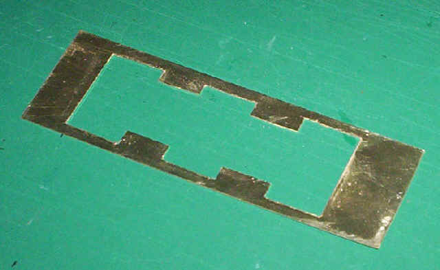
Onwards! The next step is to build the running plate unit together with its valences and and buffer beams. Once again I used 0.15" brass for this. A paper template was drawn and fastened to the brass with a couple of pieces of sellotape. Holes were drilled at all the corners progressively opening these out until holes big enough to pass a piercing saw blade through.
Although I'd got two straight edges and the all important right angle corner on the sheet of brass I decided to first of all to scribe the remaining two edges with a heavy duty craft knife. I used my trusty scissors to cut the short edges, but continued to score the longer edge with the knife. Eventually, after about ten passes I found the brass snapped off with a perfectly clean edge.
I now scribed all the lines on the section of brass to be removed and then using a piercing saw carefully cut out the centre section using the vice. Once this was removed the slightly rough and irregular edges were filed back to the scribed lines.
Construction has now proceeded as far as a basic footplate with valences and bufferbeams. The bufferbeams were cut to size from brass sheet and soldered in place. The valences are a bit of a cheat as I wasn't too keen on trying to cut out those long thin straight pieces with curved ends. Instead I soldered some 2mm wide nickel silver strip in place and then soldered small back pieces behind the strips onto which I've soldered short lengths of 4mm wide nickel silver. These were then filed to shape to give the curved ends. A strip of 2mm nickel silver was then soldered vertically in places over the end s of the valences to give the impression of the thick wooden bufferbeams. Flooding the joints with solder I then filed the curved ends as smooth as I could. Hopefully this subterfuge won't be too obvious when finished.
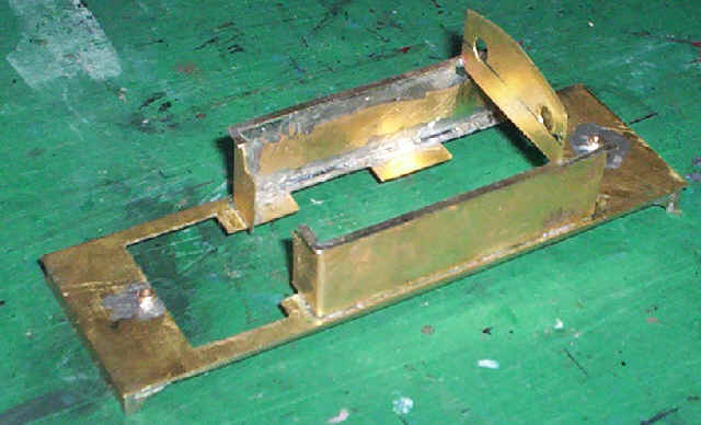
The centre line of the footplate was marked and the position for the front fixing point drilled exactly in line with the hole in the front chassis spacer. A nut was soldered over the hole and the footplate bolted in place. The rear hole was then drilled using the hole in the rear spacer as a guide. As the photo shows the chassis and footplate fit together neatly. With a couple of weights in place on the footplate the chassis trundles round beautifully smoothly and looks as though it will prove to be a useful station pilot.
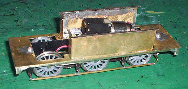
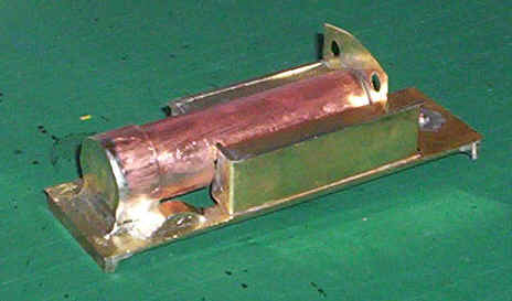
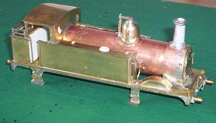
After a few week's pause on the construction of this model, whilst I was completing a rake of suburban coaches, the next stage was the fitting of the side tanks. Pieces of 70 thou brass were cut to size and then bent to give a round front corner at the front. After fixing the sides in place, the capping along the top edges was soldered in place. I used a long and short strip for each piece butt jointed at the corner and filed to a curved shape.
Here I've added the front of the cab. It only reaches just below the tops of the side tanks so as to allow plenty of room for the motor and wires.
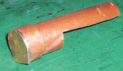
The boiler unit ready for mounting fixing to the front of the cab and to the footplate. It's made from yet another length of copper central heating pipe with a piece of brass soldered onto the smoke box front and also at the firebox end.
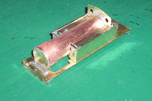
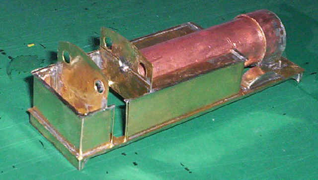
I had several false starts with the assembly of the boiler unit to the cab, side tanks and running plate, as can be seen by the waste solder still awaiting cleaning up. The final version involved :
1) soldering an extension piece to the bottom of the cab front
2) soldering a piece of brass on to the firebox end of the boiler
3). soldering a horizontal piece of brass onto the bottom of the smoke box front
4) drilling holes and then bolting the cab front and firebox together at the correct height
5) drilling a hole through the brass in front of the smokebox; this will eventually be hidden under the sloping plate below the smokebox door.
6) The small gaps between the front of the side tanks and the boiler were filled with solder and filed smooth.
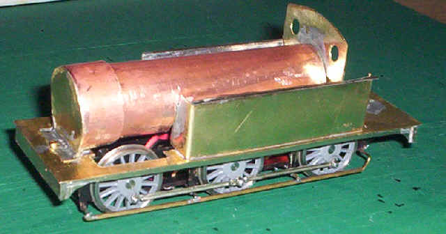
The chassis and superstructure were reassembled to check for problems; the only alteration needed was filing a small amount of brass immediately in front of the leading wheels where I hadn't removed quite enough metal and a short circuit occurred. Once again the locomotive was tested and found satisfactory, although I notice that the Portescap motor is less tolerant of slightly dirty track than the Airfix tender drives, and has a habit of occasionally surging intermittently. Adding weight seems to reduce this problem.
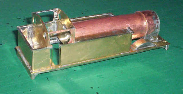
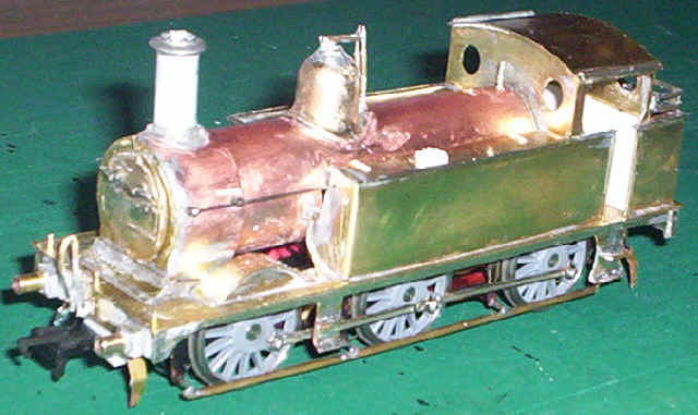
I've added the tops of the side tanks. This was a job that tested my patience! Strips of brass were cut to fit inside the tanks and abutting the boiler to leave no gap. It was a case of wiggling them into place from above and trying to stop them falling straight through the tank. Eventually, I managed to tack solder them at one end and from then on it was easy. The beading on the front edge of the tanks was replaced as it no longer butted up against the boiler. I've also now soldered the bracket at the front of the smoke box in place and removed the bolt, which will make fitting the casing below the smoke box door easier.
Some may question the wisdom of not having fitted the front wheel splashers before the boiler, but I feel that I'd rather get the heavy work out of the way first. I've also done a significant amount of cleaning up of excess solder. There are some small holes on the front of the tanks that will need some filler as I wasn't able to get the boiler to sit properly without removing more brass than I'd have liked.
I'm the first to admit that the quality of my metal work is quite poor. To be frank, it's not a material I really like working with, although I think I've improved a little over the last year or so. However, when I looked closely at the smoke box I realised that I'd made a serious error when cutting the tube. The front of the smoke box was most definitely not vertical on one side with the top being slightly further out than the bottom. Quite why I hadn't picked this up earlier I don't know. As the boiler unit was firmly soldered in place I needed to do a repair job in situ.
First I soldered a packing piece of .010" brass at the bottom of the smoke box front with another piece of .005 a little higher up. I cut a piece of .005" brass to match the front of the boiler and its associated saddle and test fitted it, this time using a square to check the vertical! Using my trusty large soldering iron this was sweated in place and solder flooded around all the joints. A few minutes work with files produced a smooth finish around the smoke box barrel.
The smoke box saddle was added using small strips of brass soldered onto the copper smoke box. Once again solder was flooded into the joints and the metal filed into a smoothly flowing curved. The extension pieces of the frames and the curved "piano" front at the front of the smoke box were cut from thin brass, filed and soldered into position.
The front wheel splashers were added next. I've had to make them slightly higher than they should be to accommodate the over scale EM profile flanges so as to avoid short circuits. Hopefully, this won't compromise the appearance of the loco too much. The splasher tops were added using brass shaped and soldered in position. The model was then given a really good cleaning up with all that excess solder being filed and scraped away.
The focus of work now shifts to the cab and bunker area. The sides and rear of the bunker are made from one strip of brass score on the inside and then filed to produce a V shaped nick which allows folding just as if it were a half-etched joint of a kit part. After soldering in place, the rear cab wall was cut to match the profile of the cab front and then soldered in place. The ridge around the bunker was soldered on using nickel silver strip.
At this point I also soldered some 1mm square section brass underneath the cab area as it was obvious that the footplate lacks strength in this area. Holes were then drilled in the footplate and the tank/ bunker beading strip for the cab hand rails. I fitted these now as it would be more difficult to do so once the cab roof and sides are in place.
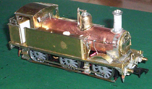
Here the cab sides have been fitted. They were cut to shape, using a piercing saw. Tidying up was done with needle files and they were then soldered in place together with a length of brass rod along the top to strengthen the very thin strip of brass here.
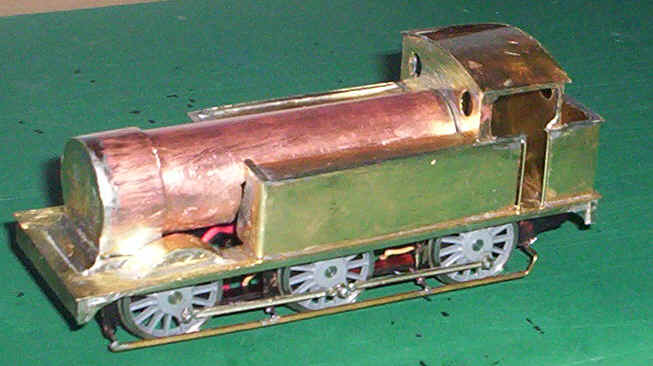
Initially, I'd intended to fit the roof much later but, as I can easily fit the boiler back head and the front of the coal bunker from underneath I decided that getting another piece of heavy soldering out of the way was a good idea. The model is beginning to look much more like a locomotive now.
I've now reached the part of construction, which I find most enjoyable. The fitting of all those small parts that brings the basic model which, at this stage could be any one of a number of very similar locomotives, into something which is instantly recognisable as a model of the chosen prototype.
Below is a list, in roughly the order I did these task, of the next batch of constructional tasks, none of which really merit a photograph.
Handrails added to front of the water tank. Lead sheet added to the side tanks and rear bunkerHoles drilled for the handrails and ejectors on the boiler.
Holes drilled and opened up for the chimney, dome and safety valve covers - lots of pretty brutal work needed hear to accommodate the spigots on Alan Gibson's lost wax castings!
Buffer pads made from paxolin sleeper strip added to the buffer beams followed by soldering on the buffer shanks.
Smoke box door glued in place with epoxy.
The Salter valves soldered to a washer on the top of the dome and also to the rear of the base of the dome.
Paper wrapper super-glued to the Society's cast chimney to give correct profile. At this stage none of the boiler furniture has been permanently fixed.
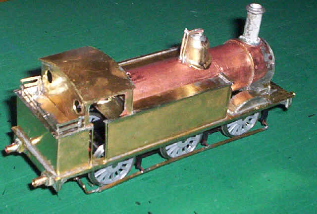
Here I've added the coal rails. A piece of brass was cut to fit inside the bunker and sit on top of the lead weight inside it. The rails were made from nickel silver strip soldered directly to this base.
 |
 |
|
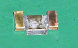
This photo shows the removable cab floor as seen from above The fixing lip can be seen at the bottom whilst the cab floor is in the centre and the splashers are on either side. Both sides of the splashers are solid as the rear of the splashers can just be seen through the cab "doors", as in the real locomotive.
|
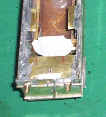
I'd been puzzling over how I was going to hide the great gap inside the cab where the floor should be. Here is my solution. After fitting a very rudimentary plasticard "backplate" to the boiler a removable floor and rear axle splasher asembly was soldered up out of brass strips. It fits in the gap between the back head and the bunker floor. The red marks on the photo on the left show the position of the "lip" of the floor section which will eventually be soldered in place.
Further stages in the assembly, which don't warrant photos are as follows:
The clack valves and pipes have been added either side of the boiler using wire and brass nuts.
Vacuum brake pipes and coupling hooks added.
Lamp irons from wire at the front.
Lamp irons on the rear bunker from very narrow nickel silver strip have been sweated on. I should really have soldered these in place from behind the bunker but completely forgot to do this before filling the bunker with lead!!
Tank fillers and stays added from plasticard to the tops of the water tanks.
The photo shows the final piece of "heavy" work on the body; the steps have been fitted on both sides. They were cut from brass sheets and strengthened behind with brass wire soldered to the underside of the footplate.
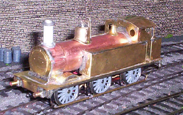
A little more progress sees the handrails in place together with the guard irons on the chassis. Test running shows that the locomotive looks to be an excellent performer and should prove a most useful station pilot. This photo shows up a slight problem with the right hand side tank. The beading on the top sloped down very slightly at the front. Gently lifting the nickel silver strip for about half an inch and then re-soldering using a straight metal edge has solved the problem. It seems like there was a minor inaccuracy in my cutting but solder has filled the gap and the top beading of the tank is now horizontal throughout its length.
The final stages of construction of the chassis can be seen hear. Guard irons have been soldered to the ends of the frames. The very prominent sand boxes are cut from Evergreen 5mm square plastic extrusions. They were fixed to the frames with epoxy and drilled for the sand pipes. These were made from .9mm brass wire soldered to the brake hanger wires. The wires protrude through the top of the sand boxes to represent the filer caps. I feel the sand boxes aren't quite beefy enough but in the absence of any better ideas of how to make four of these awkward shapes I'm sticking with them.
Construction is now finished so several was spent with files and fibre glass pen cleaning up the model before painting.
I thought, just for a change, it would be interesting to show the finished model as it would have appeared in a photograph taken in the 1920s. Here a close up of no. 1725 whilst performing station pilot duties.
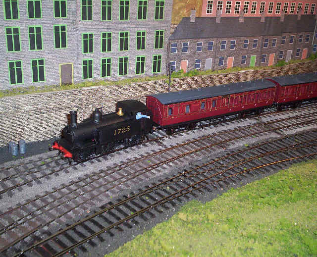
The colour photo shows the difficulty of spray painting inside the cab - the primer paint hasn't quite been covered by the black paint so clearly the paint brush will have to come out. The train behind is the latest rake of suburban coaches built using Worsley Works brass sides and ends.
As Halifax now has a passenger pilot locomotive my thoughts are turning to whether I can justify building a model of the "half cab" version for use in the freight yards. Time will tell whether I can summon up enough enthusiasm to repeat the process of building what will be virtually an identical model.