Building a MR Compound
I've long wanted a model of the MR Deeley Compound, probably as a result of a few journeys behind them in the late 1950s as a boy and seeing No 1000 on display at Manchester Central in 1961. I remember travelling behind one from between Chinley and Romiley when I was six or seven. I started talking about Compounds as if I knew all about them and was promptly told by my father to be quiet. There were two locomotive men sitting in our compartment!
In S Scale, of course, there haven't been any kits available until very recently. For some reason Alan Gibson has never produced his 4mm scale kit in S Scale . I wonder why? Some time ago I decided that I'd have a go at building one using some of the parts from a spare 990 kit that I had obtained fairly cheaply. I knew that some of the parts would be suitable and I reckoned that I'd be able to produce the extra parts I need.
One day I chanced upon Worsley Works' website and realised that they were producing some S Scale diesel shunter kits re-scaled from 3mm kits. After some discussion with Allen Doherty I ordered a set of etchings for the Deeley Compound.
Now Allen makes it clear that his "kits" aren't really kits but more a scratch-aid. This sounds just the sort of thing I like. Some of the hard work is done but there's going to be a challenge in building the model. A price was duly reached; I held my breath because the cost was slightly more than one of Alan Gibson's kits and his include castings and wheels. Nevertheless, I felt the price was reasonable for a one off, given that Allen would have to incur expense (and time) in adapting the kit from 3mm to S Scale ("Is that 4.76mm scale?" I ask!!!!). As it happens Allen has now decided that future kits will be cheaper since the one-off costs have been covered and has promised me a refund if any are sold!
The kit arrived well within the quoted time, which I felt was a welcome change from some suppliers. So what do you get for your money? The "kit" comprises a set of nicely etched brass and nickel silver parts for the body (less the boiler barrel which you have to source - in my case the 990 boiler will do nicely). Neither are there any castings. However, these are all available from Alan Gibson or, in my case, from the 990 kit.
There is a choice of smoke box wrappers, although sadly these are both for the saturated short smoke box version. I'd have liked a long superheated wrapper as well, but the kit IS advertised as a Deeley Compound. One major difference between Allen Doherty's "kits" and the other Alan's is that there are no instructions. Obviously some experience of kit building is therefore an advantage but once again I'd stress the "scratch-aid" principle.
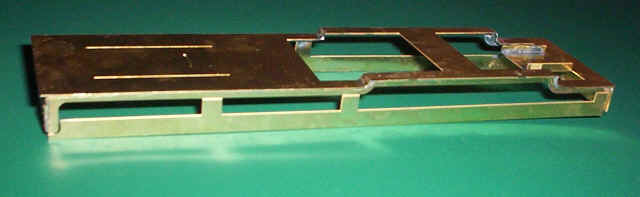
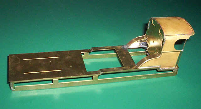
So how has construction gone so far? The first part I started on was the footplate. I'd expected this to be a nightmare as the real thing has a stepped footplate with the two ends being at different levels. However, the valances incorporate a jig which holds them rigidly in place when soldered to the three footplate sections. If you look at the photo you can see the valance is supported at four points by legs joined with a long strip of brass. The advantage of this is that when the footplate is soldered up everything stays level and it can't twist. The whole unit is like a little table and sits absolutely rigidly on the workbench (sorry kitchen table). When construction of the body is finished the legs can be snapped off at the half-etched joints.
Once I'd worked out what was intended by the designer, the construction of the footplate was an absolute joy, with the whole unit soldered up within an hour.
As usual I'm going to build the locomotive with a free rolling chassis and use a re-gauged Airfix "Royal Scot" tender drive unit as motive power. My earlier decision to go for this method of propulsion of tender locomotives has, after building three locomotives, proved to be a good concept.
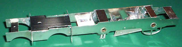
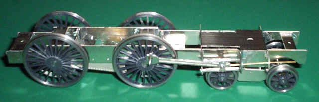
Turning my attention to the chassis I soldered in the bearings, which are a touch sloppy in the etched holes - perhaps these would have been better etched slightly under size. I used some Comet frame jigs to hold the sides rigid and in line. This is easiest arranged by turning it upside down and using the raised centre section as a datum point for levelling the frame sides. Yes, this does work with the driving wheels sitting four square on a flat surface, so clearly the frames are etched absolutely identically.
This is where I now ran in to some slight problems. The fold up "L" shaped frame spacers that are supplied are superb etchings, and plenty of them are included. However, compared to the ones I've used on my other locos (the ones from Alan Gibson's kits) they are several millimetres too wide. To have used the ones supplied with the kit would have meant that there would have been very little side play on the wheels, which is essential on my tight curves. I decided to substitute the A.G. ones and raided those in the 990 kit box. Spacers with holes were positioned at either to allow for body fixing bolts; I soldered these in place about 2mm below the top of the frame sides to allow space for the bolts which will be solder to the underside of the footplate. At this stage I did use some of the kit's frame spacers, cutting them to the correct width and adding them at various places within the frames. Once the frames were soldered up solidly I tested fitted the driving wheels; in this case I've decided to used Alan Gibson's wheels rather than Sharman's as I've got a set with EM profile treads and flanges. A quick test on the layout showed that the four wheel chassis was at square!
The front bogie was now folded and soldered up and fitted with Alan Gibson wheels. The bogie simply pivots on a bolt fixed to a spacer between the wheel arches. A few small washers were added to ensure that the front of the chassis sat level. For some reason I forgot to take a photo at this stage of construction!
I now encountered a problem which concerned the fold-up cylinder and slide bar support bracket. There are two slots in the frames that are clearly intended to accept the front of the cylinders and the slide bar bracket. However when the rear of the cylinder (this is obviously in between these two) is folded down the frames are too wide to allow it to be folded in place. This is a problem related to scaling up from 3mm with narrow frames to accept the narrow 12mm gauge. When blown up and used with frames at the correct distance apart (or close to) the fold down section fouls the frames.
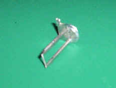
At first I couldn't see a way round this problem but then I realised it would be relatively easy to overcome this by snapping off the rear end of the cylinder, soldering on the slide bar unit and then reducing the width of the cylinder end by a couple of millimetres. The result can be seen below. Note I haven't yet removed the spacer at the end of the slide bars.
|
|
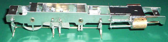
The photo below shows the frames with the folded up cylinder and slide bar bracket attached, but before the addition of the rear cylinder end. The reason for the problems in folding up this unit is caused by the kit being originally designed for the under scale 12mm gauge . The gap between the frames and the flat piece of metal in front of the slide bar bracket is the clue.
The next step was to fabricate the connecting rod and slide bar assembly. The easiest way seems to be to take one of the crosshead etchings and solder a dress making pin to it. Then solder a length of brass wire for the piston rod into the half etching on the other side. After soldering the two halves of the connecting rod together place these over the pin and finally solder the second crosshead etching to the pin at the back. To ensure it didn't all solder up solid I obviously separated all three pieces of metal with scraps of paper.
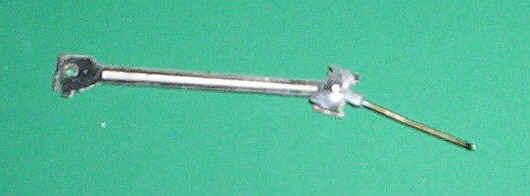
Some time was now spent fettling the slide bars and the crossheads so that they slid along each other smoothly. A tapered end was filed at the end of the slide bars to allow the connecting rod to move up and down to its highest or lowest positions. When satisfied I tack soldered the slide bars in place and after a further test soldered the rear cylinder end to the frames, ensuring that the slide bars were sloping up gently. Note that at this stage the piston rod passes through both holes in the cylinder ends. This aids visual alignment. Later on I cut the piston rod to the required length in order to allow the cylinder tail rods to be fitted.
Success! The chassis rolls along nicely without any short circuits or bogie wheel problems, even on my horrendous 36" radius curved point.
Before going any further I used my "London Road" coupling rod jigs to check that the axle holes really did align correctly with the coupling rods and to my delight they did. I should really have checked this earlier but so it was good to see that the accuracy of the chassis is very good.
The cylinder tail rods were now added. I cut a length of brass tube cut to the correct length and soldered some wire inside it. This was then passed through the two holes in the cylinder to align the tube and the whole soldered to the front of the cylinder. Once in place I cut off the brass wire and filed the inside face of the cylinder front smooth.
Brake hangers were added next; there are two types, one with half etched detail and the other without detail. Obviously these latter are intended to go behind the footsteps at the rear and front. Holes were drilled through the half etches in the frames and hangers. The brake shoes, when mounted on the cross wires, are about two millimetres away from the tread, a little far perhaps, but at least fitting the wheels will be easier and there's no risk of short circuits.
On the Compound the brake pull rods are outside of the wheels so can't be fitted until the chassis is complete. At this stage I just added cross wires through the holes in the bottom of the hangers. To make the brake gear more rigid during construction I've also soldered a wire down the centre of the chassis linking all the cross wires. I'll probably remove it once the pull rods are added on the outside.
The final job was to make some cylinder covers. These don't appear to be anywhere on the etching so I found a piece of spare brass, put it on the hob on the cooker (my wife is very tolerant!) and, once it was a turning orange, dropped it into some water. The annealed brass was then easily rolled to the correct diameter and soldered in place. A good cleaning up and the chassis is ready for painting.
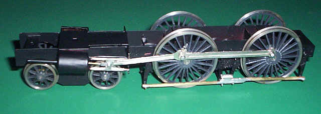
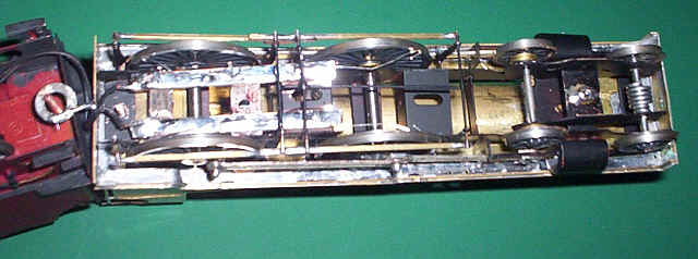
As can be seen in the photo below the chassis is now a rolling one and has been propelled over the entire layout to check for binding and short circuits. So far nothing untoward has appeared.
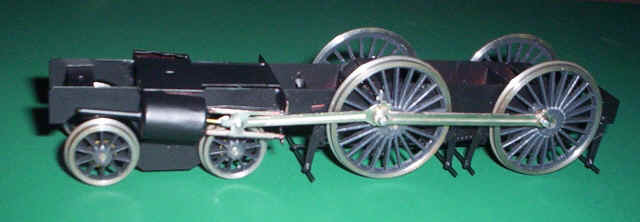
The final stage in the construction of the chassis is the addition of the brake pull rods which were fashioned from 1/16th square brass rod with a short length of tube to represent, what I presume ,is the brake cylinder
Returning to the body, the next stage was to solder up the cab and rear splasher assembly. Following standard practice, I tack soldered the cab roof to the cab front along the centre line of both parts. I then gradually bent to cab roof to shape and soldered it to the front a little at a time. Various implements (including fingers) were used for this process. Eventually with the cab sides soldered to the vertical sides of the front it was time to gently bend the splasher tops to fit the splasher sides. Half etch lines make this an easy task. I found that about a millimetre of brass had to be snipped of the splasher tops before it fitted accurately onto the footplate. This, of course, may have been my mistake as I may not have allowed quite enough overlap of the roof and sides. Once soldered to the footplate, I added the cab roof strengthening bar and the vertical handrails.
One error in the kit is that the cab front doesn't have space for the driving wheels so I had to carefully snip out the required pieces after I'd soldered the cab in place. I should really have noticed this before I did of course! Overall, however, the cab proofed easy to construct and looks correct.
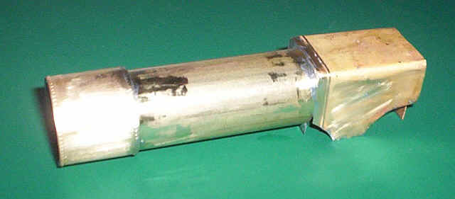
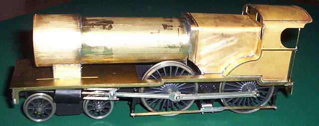
Attention now turned to the one part of locomotive construction that I dislike, the boiler and firebox. The firebox comes in three pieces; a rather thin wrapper, a front and a rear plate, The rear plate has a hole which matches the one in the cab front, allowing the boiler to be bolted to the cab front. The front plate of the firebox also has a half etched line to show the boiler position. Bending up and soldering the firebox assembly was a simple task, although I decided it was essential to sweat some thicker brass on the inside of the wrapper as this is so thin any pressure will deform it very quickly. I used the boiler tube from the 990 kit, which is the correct length for the superheated compound, and soldered this to the front of the firebox. The shorter tubing for the 990 smokebox (cut lengthways, of course, to allow it to slip over the boiler tube) and the etched smokebox wrapper were then soldered together. I hate this job!
The next stage is to solder the smikeboc saddle to the underside of the smoke box. I did this on the inside of the fold up saddle. The sides of the saddle were cut from part of one of the Worsley Works smoke box wrappers, one of which includes the section needed. These were then soldered in place. To secure the boiler unit to the footplate and cab the firebox was bolted to the cab and the smoke box was centred between the half etch marks on the footplate. I then drilled a hole through the underside of the footplate and up through the smoke box saddle and into the smoke box itself. After countersinking the hole on the underside of the footplate, the boiler was then bolted to footplate with a countersunk head bolt.
The next task was to solder the firebox sides to the rear of the splashers and to the footplate.
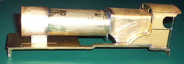
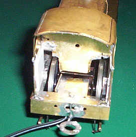
At this stage I snapped off the valance jigs to allow the chassis to fit easily in place. A test fitting of the chassis showed that all was well. The model is now beginning to look something like the Compound it's supposed to represent, although I have some doubts about the proportions at the smoke box end of the boiler.
One thing that is immediately apparent from this shot is the large flat area under the boiler where there should really be a great big hole between the frames. Once again this kit is betraying its TT origins. In order to hide the cylinder and slidebar assembly (which fill up the space between the frames as well) the footplate has been designed as a continuous plate under the front of the boiler. In retrospect I should probably have cut away both of these pieces of metal but now, short of some drastic surgery I'm probably stuck with them. I do feel that the plate between the frames can be cut away leaving the slidebar bracket across the frames. Likewise I think it should be possible to cut away the excess footplate if I'm careful.
The next stage of the construction was the fitting of the front splashers. I decided, once again, to use a part from the the 990 kit; this time it was the splasher tops. Once solder to the splasher fronts these need to be trimmed to fit against the boiler. There were some pretty awful gaps between the firebox and the splashers which have needed filling with solder. So far this is the only part of the kit which doesn't seem to have been drawn quite correctly.
Thankfully, cutting away the unwanted pieces of brass and nickel-silver wasn't a difficult task with my Exacto microsaw. It would have been less nerve-wracking though if I'd thought of it earlier!
Having reached this stage I decided it was time for a proper test of the loco on the track. I fitted some copper clad sleeper strips to some of the spacers and soldered nickel silver wire in place for the pickups. I decided that the springs behind the driving wheels were hardly visible and would get in the way of the pickup wires so I snapped them off. Operational features always come first as far as I'm concerned.
|
|
A simple drawbar of some brass wire and a washer was fabricated and soldered to the loco drag beam. I now decided to test the Compound using the powered tender from my completed 990. The wires were unsoldered from the 990 loco and re-soldered onto the Compound. It became immediately apparent that all was not well! The loco kept derailing and it ran rather erratically and there were sparks flying about. Investigation showed that the rear bogie wheel was touching the crossheads; I'd expected this problem and was surprised not to have encountered it earlier. The derailments were obviously related to the same problem.
The solution was amazingly simple. The rear bogie axle was packed with washers to allow only just enough movement to allow rotation. Ensuring that the bogie frame was centred I tightened the pivot nut. Placing the loco on the track now showed that the short circuiting problem was solved. I reamed open the front axle holes to give some vertical slop and placed a double coil of solder onto the axle to give these wheels some weight. Thankfully the loco now runs smoothly and will just traverse the really tight curve in the freight yard. Since it's not going to run there I feel confident that the rest of the layout with its more generous curves should cause the model no difficulties.
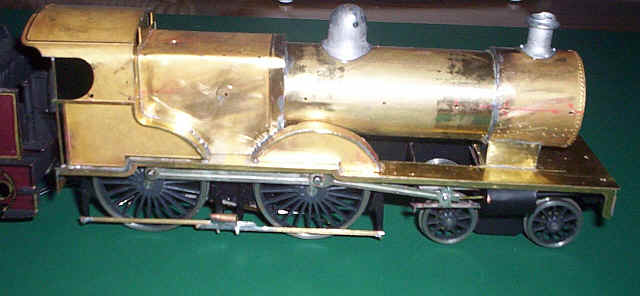
A long session has seen considerable progress being made. On the loco the steps, boiler front, reversing rod, lamp irons and various handrails have been added.
The tender body and outer frames have been built almost as intended. I've added the usual support brackets inside the tender to allow the fitting of the Airfix tender drive I use as standard on my tender locos. Unfortunately this does mean that the tender wheelbase is incorrect, but its possible to disguise this by adjusting the position of the axleboxes and springs. More details can be found on the locomotive and tender drive page. In order to access the fixing screw at the rear of the tender drive unit it is necessary to drill a hole through the tender top to allow a screwdriver through. I've strengthened the rather thin sides with a second layer of brass sweated in place.
A little more progress sees the smoke box door, handrails, and tender axle boxes and springs in place. These have come from either the 990 kit or the body of an Airfix Royal Scot. The handrails of this model being exactly the correct distance for the Compound! The low frame version of the Compounds had these raised plating around the smoke box which I've replicated using 60thou plasticard. The model is now basically complete apart from some plastic work in the cab and a little weight in the tender.
The photo below shows the cab interior. I decided to build the wheel covers inside the cab out of plasticard rather than use the etched ones in the kit. I might have made a mistake in how to use them but I found as folded up they fouled the wheels. A few minutes work with some plasticard saw two box like structures and a raised footplate in place. The boiler end and firebox details came from a casting in the 990 kit.
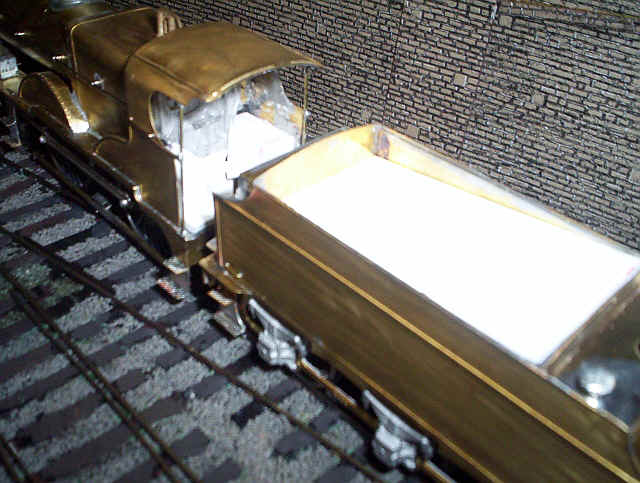
Returning to the tender the final task was to Araldite some supports inside the tender sides to support the removable and sloping top which will eventually be covered with coal. Some lead has been added to various places inside the body of the tender. Plasticard pads were added to the rear of the tender body behind the buffer beam to support the Bachmann plug in coupling box as described in the couplings section of this website.
Running trials with the loco have proved that the engine can easily haul the sort of train I anticipate it heading; It handles the equivalent of seven bogie coaches with ease.
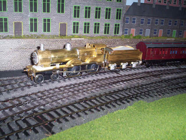
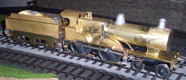
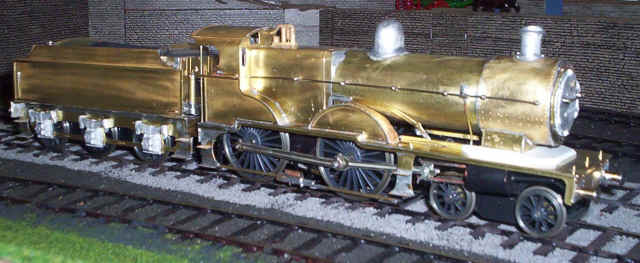
The Compound shortly before entering the paint shops.
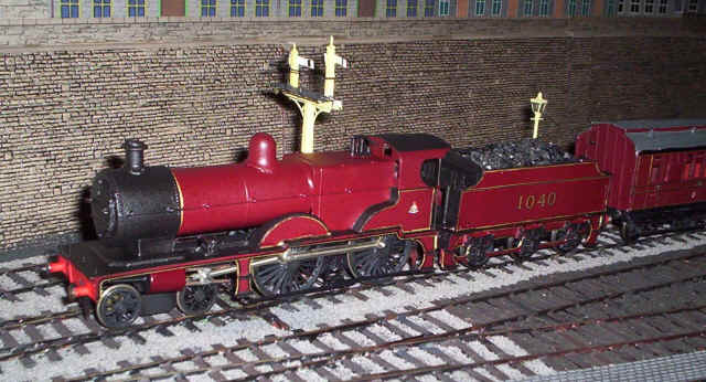
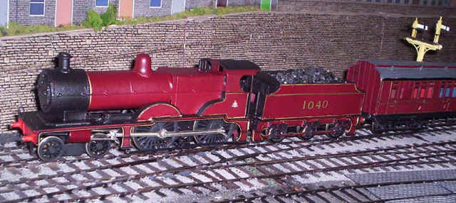
Two views of 1040 leaving Halifax on a train to Leeds. I've now started to use a Pilot gold marker pen for the lining as WH Smith have discontinued theirs. The Pilot pen has quite a fine line which appears to come from a metal tube and is easy to control, either freehand or with a ruler. As usual the black line is drawn with a Staedtler fine overhead projector pen. The results remain a little rough and ready but I've decided in the interest of consistency to stick with my existing methods.
The only problem with having a Compound is that I now really want a main line layout. Any ideas how to cram that into my limited space would be more than welcome.