Building an LNWR G2 0-8-0
For my next modelling challenge I've decided to tackle an etched brass "kit" of an LNWR G2 0-8-0.
As part of the job lot of S Scale items that I purchased from Alan Gibson many years ago there were some etchings for the loco body and tender of one of these distinctive locomotives. The kit is a scaled up version of the old Brassmasters 4mm scale kit.
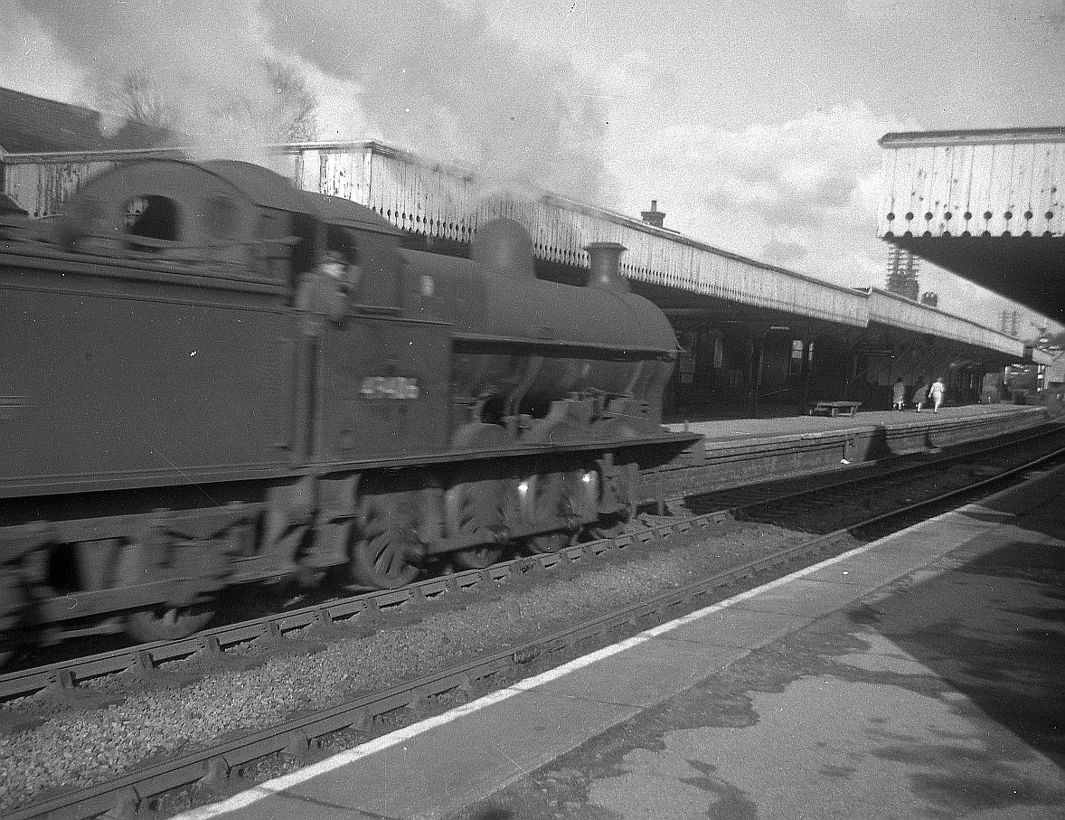
In the early 1960s I saw quite a number of these locos in service. This is Buxton shed's 49406 seen at Miller's Dale on a freight to Rowsley. The photo was taken by my father on my Brownie Cresta box camera.
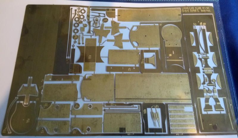
This fret holds most of the parts for the loco body.
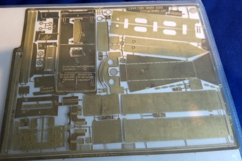
Whilst this one is for the tender.
There is also an assembled outer tender frame with those distinctive steps
There are no loco frames in the parts I have so these will need to be made. For once good fortune stepped in as the G2s have absolutely identical axle spacings to the Somerset and Dorset 2-8-0s. I have several etchings for the Alan Gibson S Scale model of the 2-8-0 which means that I will be able to use the coupling rods to mark out the G2 frames accurately.
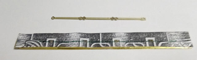
Fortunately I do have photocopies of the etches so after resizing these to the correct dimensions I've used these as a template for the frames.
Two rectangles of brass sheet were cut roughly to the correct size and tack soldered together. The paper template was glued to the brass. Then I drilled a pilot hole for one of the axle holes in the correct position. Next using the S&D 2-8-0 rods the other three holes were drilled. This should mean that axle holes, crankpins and coupling rods should line up automatically. I suspect I may end up splitting the rods into three sections, as with four axles to quarter and tight curves to be negotiated, I think it is unlikely the chassis will run smoothly unless I do. Luckily the Gibson kit comes with four sets of rods so this will be a simple task.
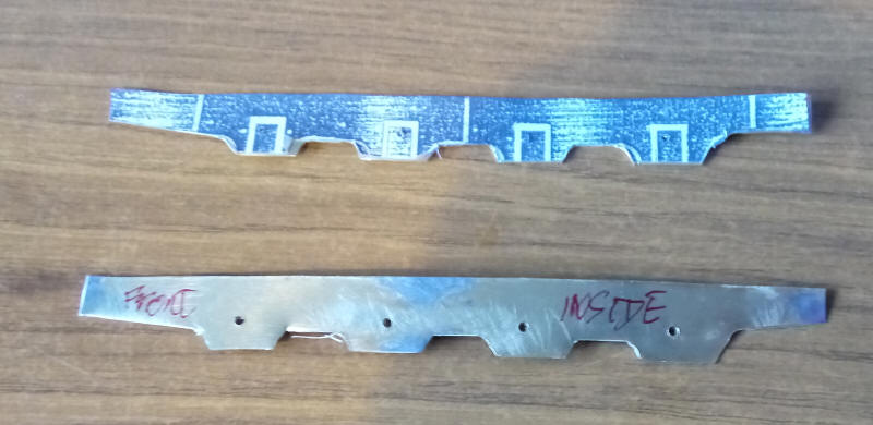
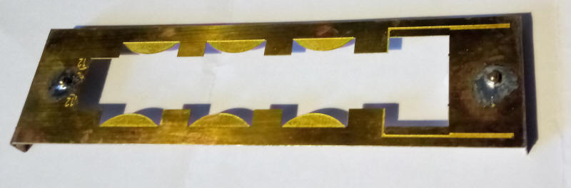
I've now cut out the main frames. The cut outs at the ends of the frames were made using scissors. The three cutouts between the axle holes were made by first scoring the brass along the straight lines with a heavy duty Stanley knife and then snipping the short diagonal lines with scissors. The small sections of brass were then broken loose using a pair of pliers to bend the metal until it broke. The corners were slightly rounded with a file. It's a crude but reasonably effective method. The axle holes will now be opened out with broaches and bearings fitted.
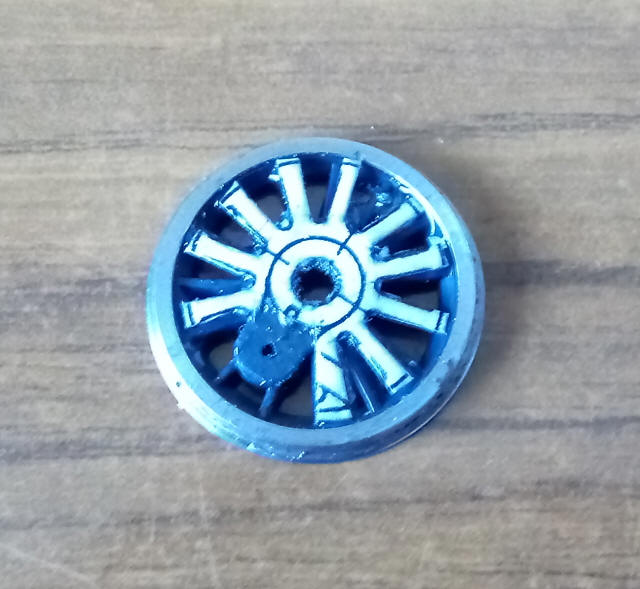
The real problem building a LNWR 0-8-0 is, of course, the highly unusual driving wheels. Having looked at the 4mm scale Brassmasters kit (where a etched brass overlay is glued to Gibson wheels) I decided to experiment by printing out an S Scale sized drawing of a G2 onto thin card. The card was then coated with wood hardening fluid and later I cut out the space between the spokes.
The card was then glued on to the correct size wheel with epoxy. A thin smearing of epoxy was later added to the top of the card and also underneath the card between some of the plastic spokes.
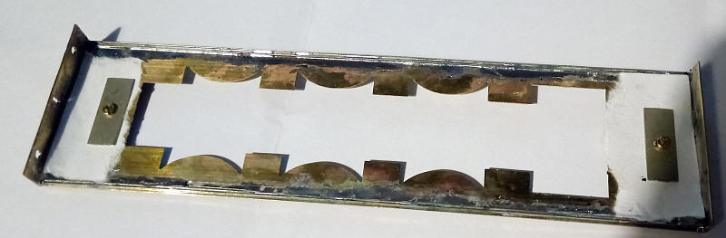
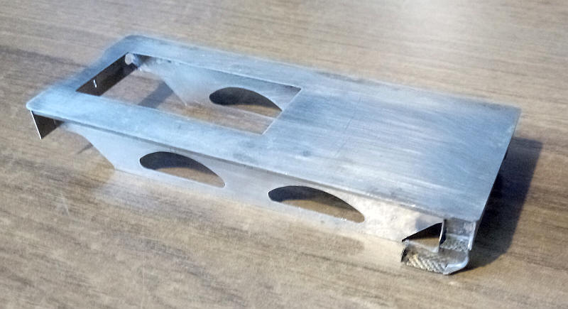
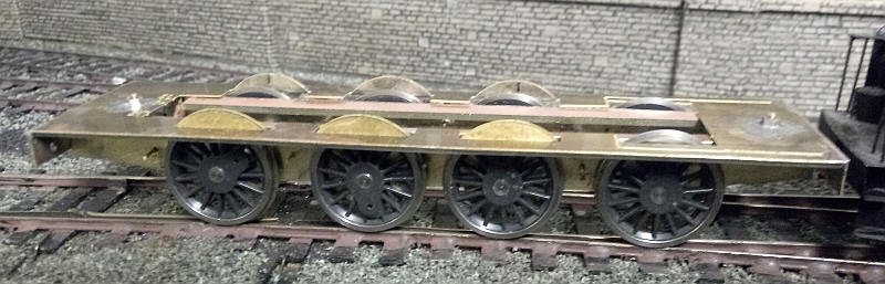
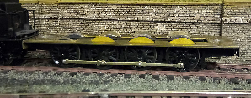
The basic footplate structure has been assembled. The lower photo shows the valances which are lengths of code 45 rail soldered to the underside of the footplate. The bufferbeam and drag bar have been added and the front and rear spacers and their associated nuts and bolts are in place.
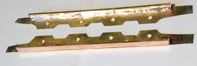
The frames have been strengthened using the same method I adopted for my German V60 diesel shunter. Lengths of double sided copper clad sleeper strip have been soldered along the top edge of the frames.
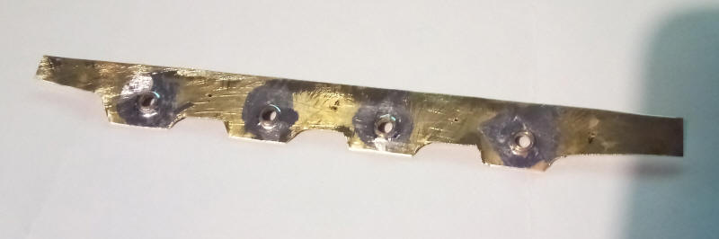
Rather than use top hat bearings (which I've run out of) I soldered axle washers to the axle holes in the frame. These were later filed much thinner to allow sufficient side play and the middle two holes were elongated at the top by filing to allow the centre wheels to rise slightly over rough track.
The front of the wheel splashers have been bent up and Alan Gibson wheels have been temporarily fitted to the chassis. When being propelled by a powered tender this revealed (as expected) some spectacular arcing as the backs of wheels touched the back of the splashers. Otherwise the chassis rolls well.
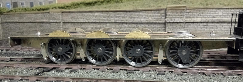
I've now added the brake hangers and the wheel on the third axle has had its flange filed away. Smaller brake hangers are need between the second and third wheels as the wheel spacing is much closer here.
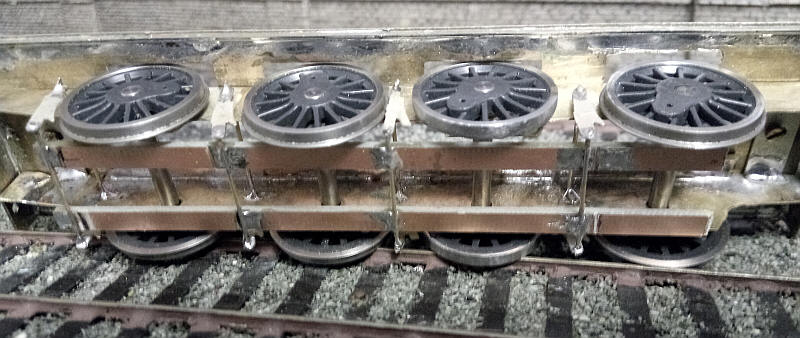
Viewed from underneath, the flangeless third wheel is more obvious. Careful filing can produce a wheel that doesn't have its tread damaged. To avoid the flangeless wheel cause problems catching on check rails or simply falling off the rail on curves I found it necessary to limit the side-play on both the third and fourth axle to a minimum.
The lengths of copper clad sleeper soldered to the brake hangar cross wires will be used to provide current pickup form the outer axles. The copper is gapped to give isolated sections of copper behind the wheels.
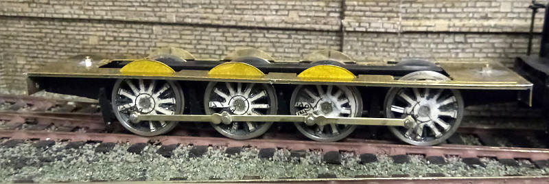
The chassis is now complete and rolls smoothly. The rods are in three sections with the S&D 2-8-0 rods cut to overlap at the crankpins. I placed two very small washers over each of the crankpins to ensure that the back of the rods don't rub against the card spokes.
The wheels after painting one side of the chassis black.
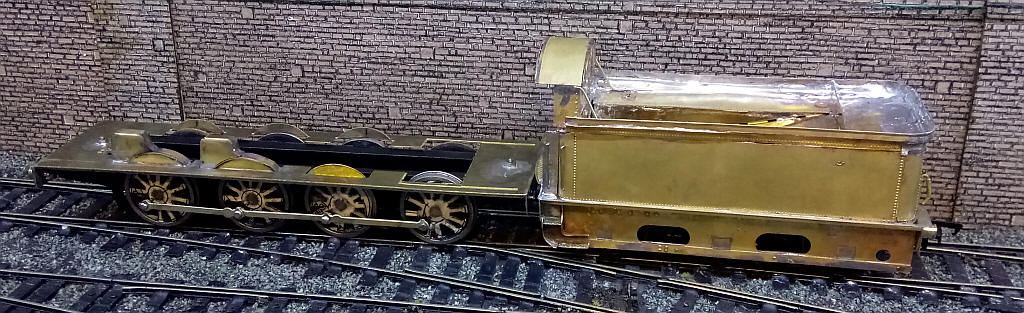
I've now assembled the tender. The power unit couldn't use my standard mechanism with two Mashima 1624 motors driving two Markits gearboxes as the LNWR tender very different to midland tenders and I wanted to be able to show this on the completed model. The drive unit has actually come out of one of my Midland Railway 3Fs which has a single large Mashima motor with a long drive shaft and drives two gear boxes. The profile of the motor and gearboxes is sufficiently low as to allow the etched brass tender to be built as intended.
Construction of the tender body was not the easy as the flared upper part of the sides and ends have to be assembled for five different parts soldered to the top of the sides and ends. The Midland Johnson tenders for Alan Gibson are considerably easier to assembled.
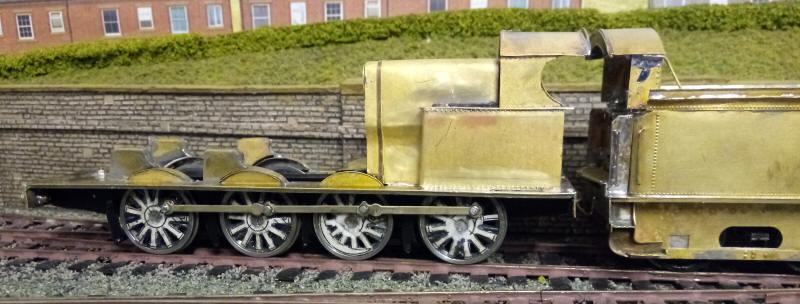
The cab and firebox have been added. Construction was not easy as getting the parts to fit was difficult. The kit is very old and for instance lacks half etched lines for bending parts.
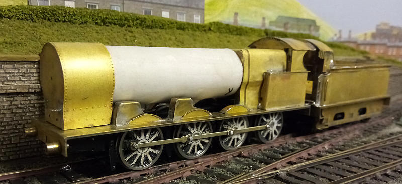
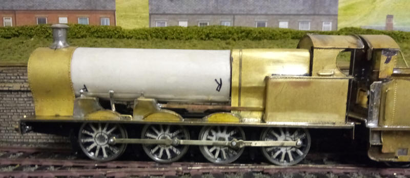
The smokebox assembly and the boiler are now completed but not yet secured. The boiler is made from a length of plastic piping with a strip of card wrapped around it to build up five layers. The leading edge of the card is first secured to the pipe with impact adhesive and then the underside of the card has a thin layer of two part epoxy resin spread over it. Once the card has been rolled around the tube three elastic bands hold the card layers tightly in place until set. The joint in the card will be concealed at the bottom of the boiler. The card has been coated with wood-rot hardening fluid.
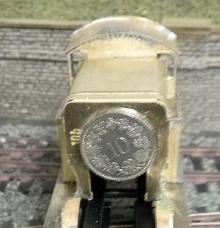
The boiler is secured in place at the smokebox end by sliding it inside the smokebox wrapper but the method I've chosen to secure it at the firebox end is unusual. A Swiss coin - a 10 cent one - is glued to the front of the firebox with epoxy. The coin is a perfect fit inside the plastic inner tube of the boiler.
The loco begins to look like a G2 0-8-0. The chimney is a cut down Alan Gibson casting - I'm not sure what it was intended to be but by cutting of the top just under the rim, followed by cutting off about 2mm from the remainder of the casting a chimney of the correct height was obtained. Filing away a little of the metal at the bottom of the chimney gives a slightly tapered in profile. The result is very close to the LNWR chimney.
Various handrails have been added as well as the reversing rod and the control rods for the sandboxes made up out of wire and strip metal.
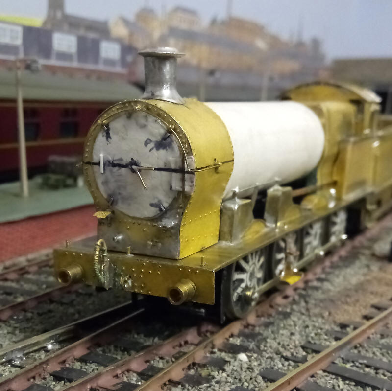
The smokebox front requires a lot of work to get something looking like a LNWR loco. The smokebox door is a disc of card which has 3 further discs glued underneath it each decreasing in size. This assembly is then glued with superglue onto a sheet of card with the edges of the top disc pressed down, thus giving a slightly domed effect. Various other pieces of card, microstrip and wire are then used to represent the dart, hinge, handles and securing cleats.
The handrail knob holes were drilled and wire bent to shape and the handrail knobs secured with superglue one at a time until completed.
The model is beginning to look like a G2 0-8-0.
I hadn't decided at what stage to glue the card boiler to the metal but after giving all the brass parts a good cleaning the firebox, boiler and smokebox were all assembled using Devcon and a soldered joint under the smokebox.
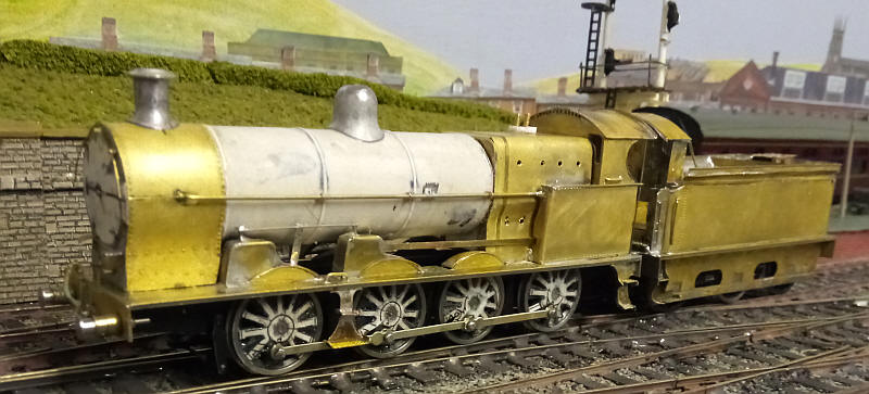
The dome is an Alan Gibson white metal casting slightly modified to give a more rounded top. The boiler bands are 10 thou microstrip solvented to the card boiler. The 0-8-0s seemed to have a very thick longitudinal handrail (in this case 1mm brass rod) which doubled as a pipe to the smokebox. The handrails were held in place by copper wire wrapped around the wire and superglued into holes in the boiler. The holes for the washout plugs have been drilled in the firebox.
I've also soldered a small piece of brass to the handrails behind the dome to act as a location point to what appears to be a box with lubricating pipes coming out of it. These will be added later.
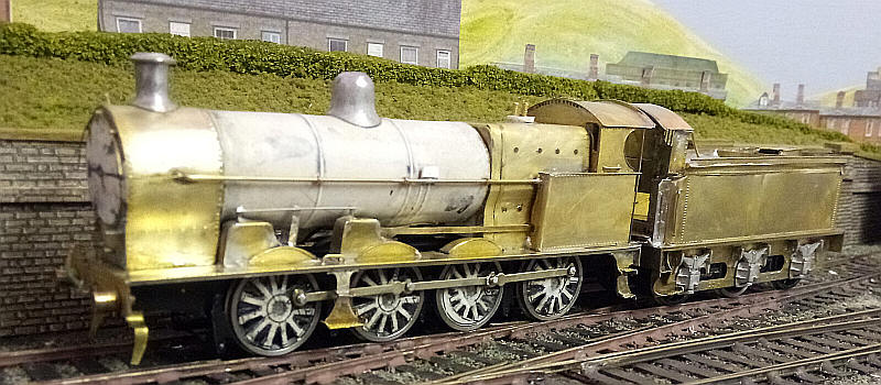
Construction is now complete and the model is ready fpr painting. There are more details I could add but there is always the risk that these detract from the basic simplicity of the model. I've added the guard irons to the front of the chassis and some pipework from the small box on the side of the boiler as well as giving the washout plugs a backing of filler inside the firebox. The tender now has its springs and axlebox castings. I believe these may be intended for Midland Railway tenders but they are very close to those on the LNWR tenders so will have to do.
The construction time has been about three weeks of intermittent work.
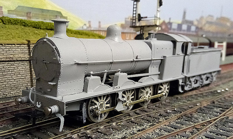
The loco has now been painted with a grey primer and has had pickups fitted to the leading and rear driving wheels in addition ot those on the tender.
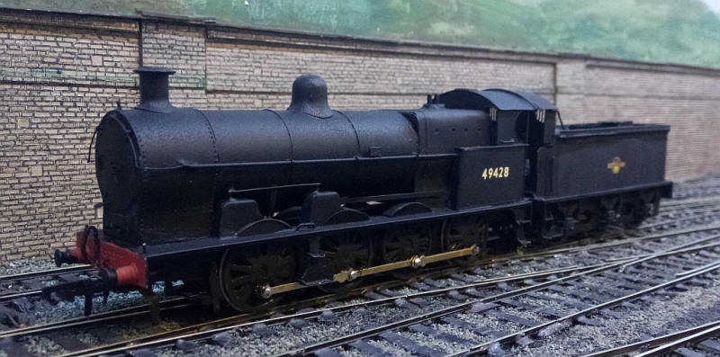
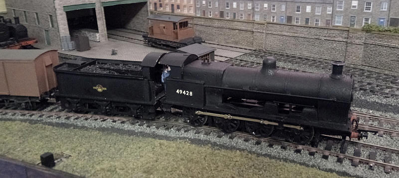
The finished model of 49428 which I saw at Carnforth in 1962.
I've given it an ex works finish at this stage with weathering to follow later. A small number of 0-8-0s received the later BR crest so I've decided that, since 49428 survived into 1962, it may have been paired with a tender with this crest.