Deutsche Bundesbahn 3-axle Umbauwagen
I've had an interest in German railways since my first visit 45 years ago when I was captivated by the Deutsche Bundesbahn. Later I modelled German and Austrian railways for many years in Z, N , TT and HO scales but eventually moved back to model my other great love, the Settle and Carlisle railway in 4mm scale. Needing a different type of model making, with more scratch-building involved, I then started work in S Scale, Halifax Midland and Hebblethwaite being the outcome.
But my fascination with German railways has never gone away and recently I've started to get the itch to model them again. However, spending hundreds of pounds on models that anybody can buy no longer appeals. I wondered if I could combine German modelling and S Scale.
There is a big interest in Germany in computer generated cardboard kits. Many of these are available as free pdf downloads on internet forums. After joining one or two forums I discovered that there are sufficient kits available to model a DB branch line in the 1960 to 1980 period, exactly the time that appeals to me. The downloads include four types of diesel locomotive - a four and a six wheel shunter, a centre cab BoBo and a larger main line BoBo. Coaching stock includes the standard 3 and 4 axle post war rebuilt coaches known as 'Umbauwagen'. There are also numerous freight vehicles in similar pdf kit form.
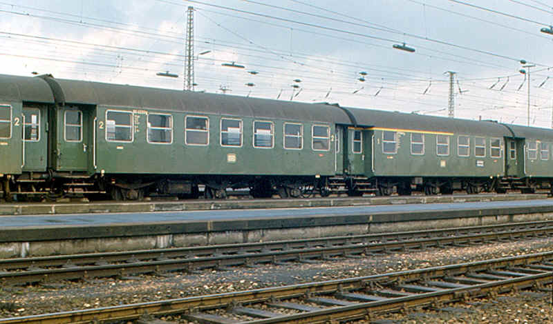
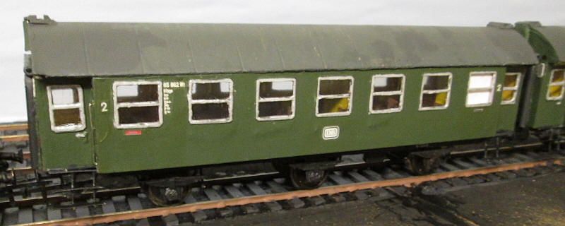
A train made up of 3 axle Umbauwagen at Heilbronn
(http://de.wikipedia.org/wiki/Umbau-Wagen_(DB))
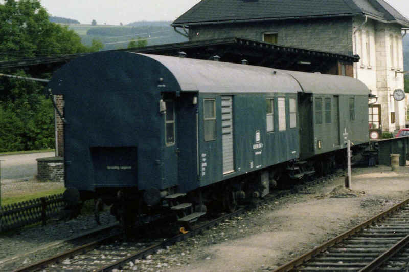
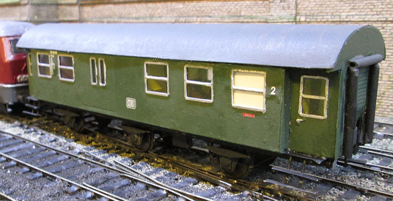
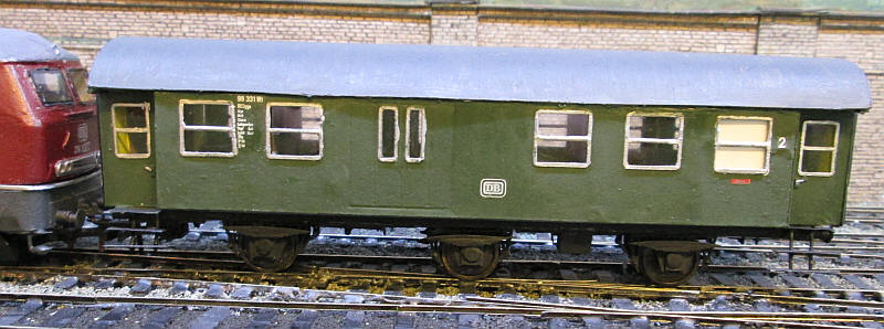
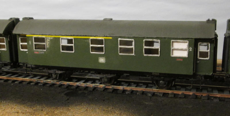
Photo of two Deutsche Bundesbahn three axle 'Umbauwagen' seen in August 1980 after withdrawal from passenger service and now in use by the engineering department. I believe the one nearest the camera was originally an all second class coach whilst the green one was a 2nd class with conductor's accommodation as.
The main problem is that these kits come mainly in O Scale but by doing a screen print of each page of the pdf and then resizing the resultant jpg image you can end up with S Scale sized pages. To do this all you need is one or two known dimensions, such as the length of the wheelbase or coach side and set your image to that dimension in cms.
Below is one of these images -
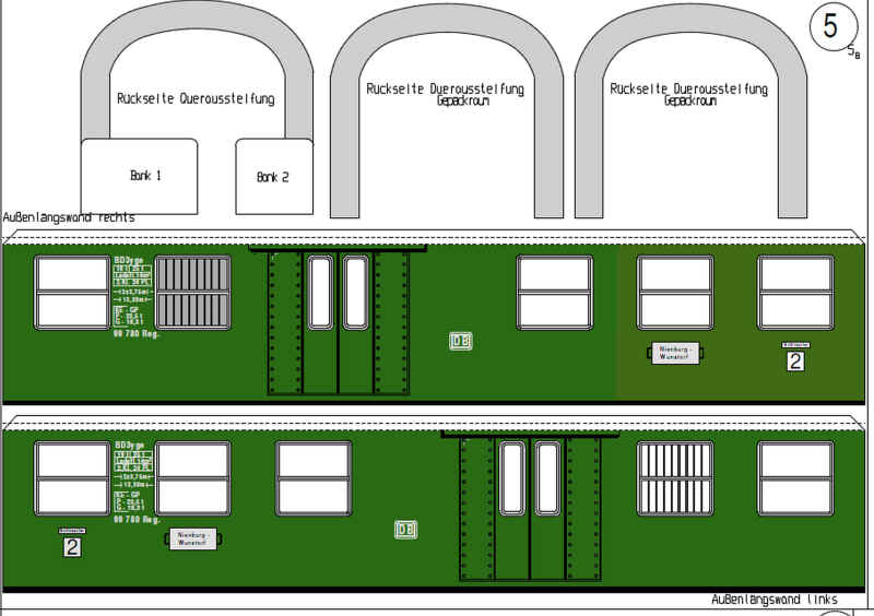
This was resized to give the correct S Scale length of 17 cm for the coach side. I then printed out the image twice in black and white on 140 gsm white card.
As these carriages all had a very distinctive unpainted metal window frame the first task was to make these. I ideally I should probably have ordered etched window frames but this is meant to be a economy project!
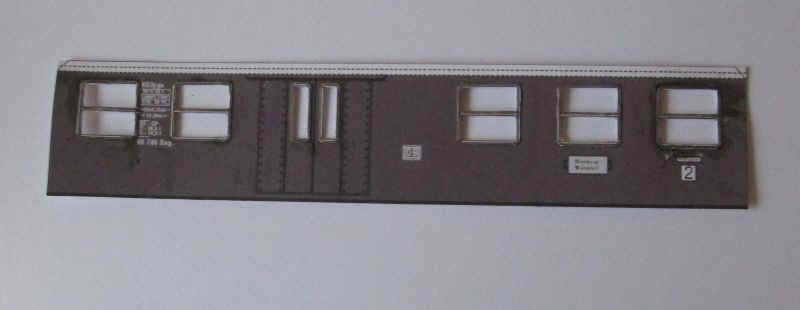
The first stage is to cut out the all the window frames from one of the coach sides. The corners of each of these rectangles was rounded off by making a small diagonal cut. Each of these 'window' units was then glued directly on top of the windows on the second sheet of card using PVA adhesive. After the adhesive had completely dried I used a sharp compass point to prick holes through the two layers of card in each corner of the windows. Then the openings were cut out carefully with a scalpel blade, making sure not to cut through the card at the ends of the horizontal window bar. Although these seemed remarkably strong I decided to strengthen them by running Loctite 'superglue' around all the window openings. This makes that centre bar really strong - almost like metal in fact.
Note: the photos may appear to be in black and white because I printed out the sides in B&W rather than colour.
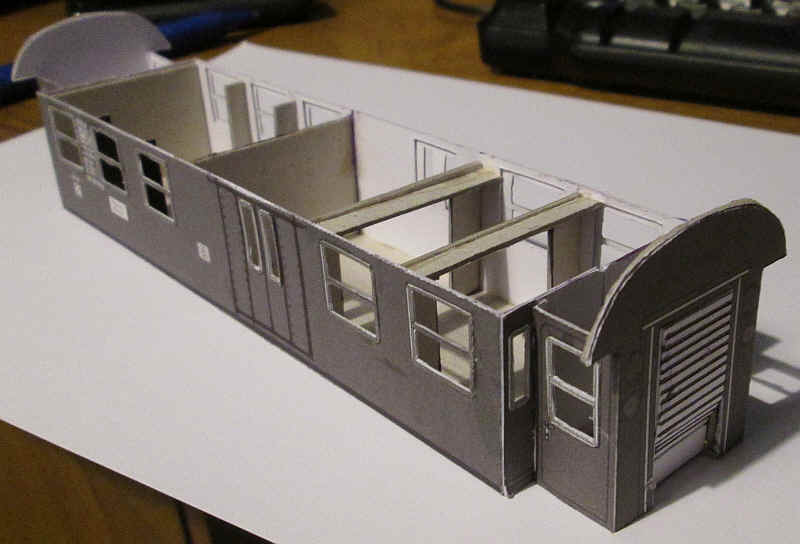
Having assembled the two sides the next stage was to add two inner layers of the sides. The middle layer has slots for the glazing strips to be dropped in palace from the top and was glued to the back of the outer side. The inner layer which has openings slightly larger than the sides was glued in place on top of the middle layer (see diagram below)
Both the middle and the inner layer have folding half ends which will fold around the floor of the carriage body. I made this slightly less than half the width of the body.
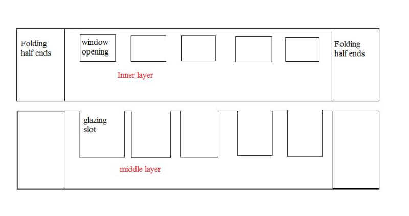
To complicate matters slightly the conductor's end of the coach has two narrow vertical windows in them so more window openings have to be cut in the folding ends at one end. These will be glazed after painting and before the roof is fixed in place.
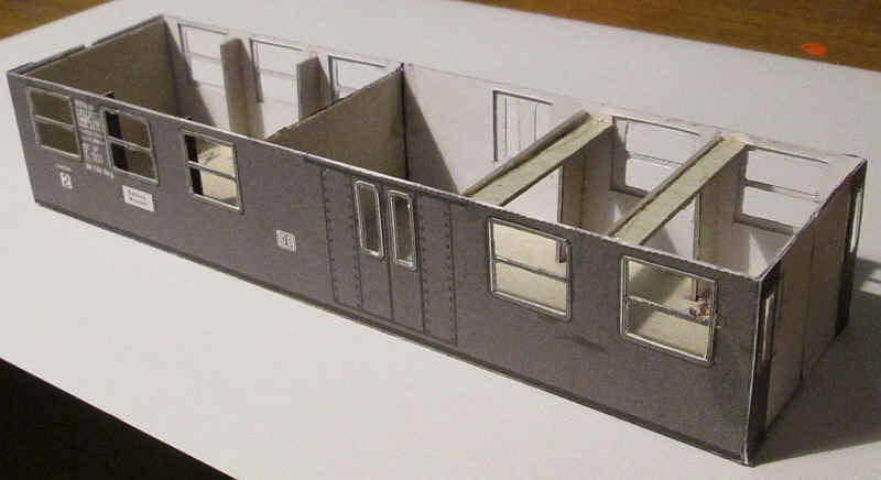
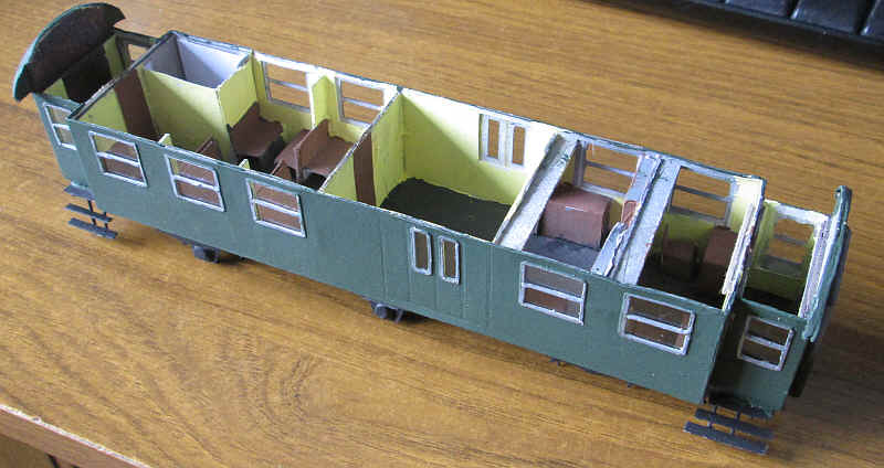
A 1mm thick piece of card was cut to size for the carriage body floor and the two sides/ folding half ends were glued in place. The two half ends were secured together with a strip of the thick card inside the body. These strips will also act as support for the removable roof. More on this later. At this stage I also glued in place the narrow guard's end window panels.
To complete this stage of construction I added various pieces of thick card to both keep the body sides rigid and support the roof. You may notice that in the passenger compartment at the far end there are vertical strips in between the windows. These are actually present in the real vehicle and were intended to reduce draughts when the windows were opened.
The next stage in building the coach body was to add the two ends with the passenger doors. These are considerably narrower than the main body as this enables the steps down to platform level (remember German stations often had platforms almost at rail height) to be contained within the loading gauge. The kit contains both outer and inner layers to these ends which are designed to fit inside each other.
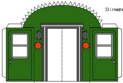
After cutting out the windows from one set of ends, I glued them in place on the outer layer - just like I'd done for the sides. The window openings were then cut out followed by trimming off all the tabs along the roof edge. A cut also needs to be made along the top of the door to allow it to fold inwards. After scoring along the dashed lines the outer end unit was folded into shape.
I then used the inner ends that had had their window units cut out to form the inner strengthening layer. I also enlarged the window openings to allow the glazing to be glued in place after painting. The small tabs along the curved roof and the top of the doors were cut off, but those by the side of the doors were left in place.
The two units were now glued together and fastened to the main body of the coach using the tabs by the side of the doors.
One area where the kit over simplifies things is the end roller shutters of the corridor connection. Deutsche Bundesbahn's solution to corridor connections was well ahead of its time. The openings at the ends of the vehicle had roller shutters which were raised into the body ends. A metal plate was then dropped down to act as a bridge to the next vehicle. These six wheelers were closely coupled, whilst the corridor connection itself was a rubber tube that compressed when vehicles were coupled.
To represent the corridor connection I'll probably use plastic tube, whilst the roller shutter with its distinctive curved lower half is made of a piece of curved card scored with a biro.
I anticipated that making the roof would be the most difficult part of the construction of the body as the roof merges almost seamlessly into the body sides. The roof needs to be detachable as glazing of the windows will be done by dropping the glazing strips into the widow slots from above.
In fact the roof proved to be much more of a problem than I'd anticipated and I had three unsuccessful attempts so rather than bore the reader with the failed attempts I'll leave this until much later in this description.
The underframe and chassis
Having constructed the basic body of the coach I decided that the next step was to build the carriage's underframe and chassis.
The chassis will use the etched brass Cleminson 6 wheel kit produced by Brassmasters and available through the S Scale Society to members. I'd already built several for my Midland Railway layout so I knew they are easy to build and reliable in operation. In fact this model will go around a 36" radius curve with no problems.
The underframe was going to be built out of card using some adapted parts from the Pirling pdfs. These are described as Rahmemunterteil (frame under parts) . The kit produces them in two sections which are glued on to the upper frame parts. I wouldn't be using these. Below are the two sections from the pdfs.
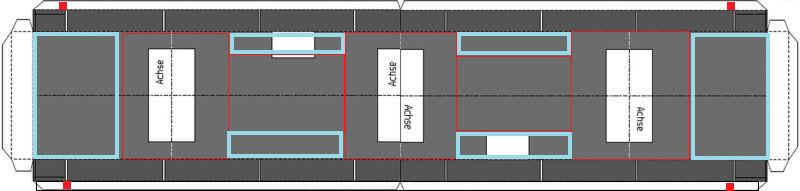
Having rescaled the parts and joined them together I drew them out on card with the alterations shown below.
The long tabs marked with red squares were made much wider - 15mm which is half the width of the frame width - so that when the frame "box" was folded up they were exactly the same width as the bottom of the frame.
The areas marked with red rectangles were cut out leaving the card marked with the blue rectangles in place. These cut outs are to accommodate the chassis parts. The photographs below will hopefully make this clear.
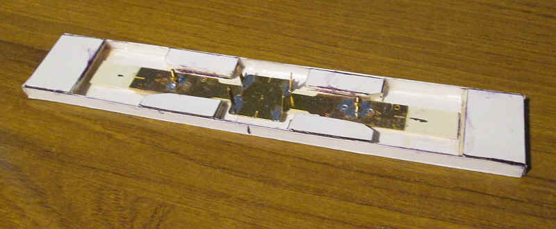
This photo shows the underframe viewed from the top. The faint mark down the centre shows where the two halves of the widened tabs are joined.
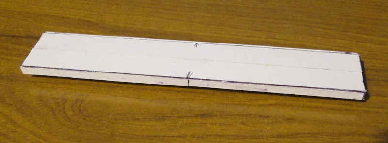
Turning the underframe over, the areas where card has been removed can be seen with the remaining large parts at the ends and smaller parts along the sides. To strengthen the frame three layers of thick card were glued in place under the end pieces and under the four narrow sections along the sides. A further layer of thick card was glued down the centre of the frame and the brass mounting strip for the W irons and wheels was glued in place using epoxy resin. A strip of card 5mm wide was glued along the narrow edges of the frame and a thin layer of epoxy was also spread along the inside of the edges to give additional strength
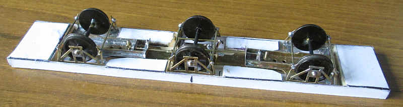
The photograph below shows the assembled chassis which will negotiate very tight curves - 36" (900mm) radius.
Another problem
Having got to this stage I realised that when I placed the body on the chassis the proportions all looked wrong with it being obvious that the frame was too deep and the model was sitting too high. I suspect that a combination of the the folds and some slight error in my measurements caused this so I started again. This time I made the narrow edges of the frame 3mm deep instead of 5mm. The result is a much better proportioned appearance and a completed frame depth of 4mm. I also cut away the diagonal bracing on the W irons as the DB coaches don't have these.
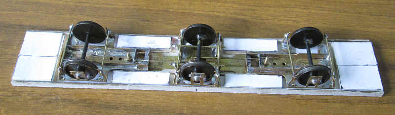
Attention now turns to detailing the chassis. Whilst I am using card as much as possible I don't think it's the best material for parts that will be handled a lot. In this case the springs and axlebox covers will be subject to a lot of wear and tear so I'm building them out of plastic.
The springs are made from layers of 15 thou plasticard. Seven pieces, varying between 25 x 12mm and 7 x 12mm, were glued on top of each other with solvent. Once dry six strips 2mm wide were cut from this to form the springs. The axleboxes were cut from 20 thou 10 x 5mm with a hole drilled to locate them over the pinpoint bearings. A trapezium shaped back plate of 10 thou was glued behind the springs and axlebox.
With the axleboxes and springs secured in place (and one of the attempts at the roof perched on top of the body) I've placed the carriage body in the correct place on the chassis. The gaps at the end of the body are correct as the Umbauwagen were close coupled and the buffers were actually underneath the carriage ends.
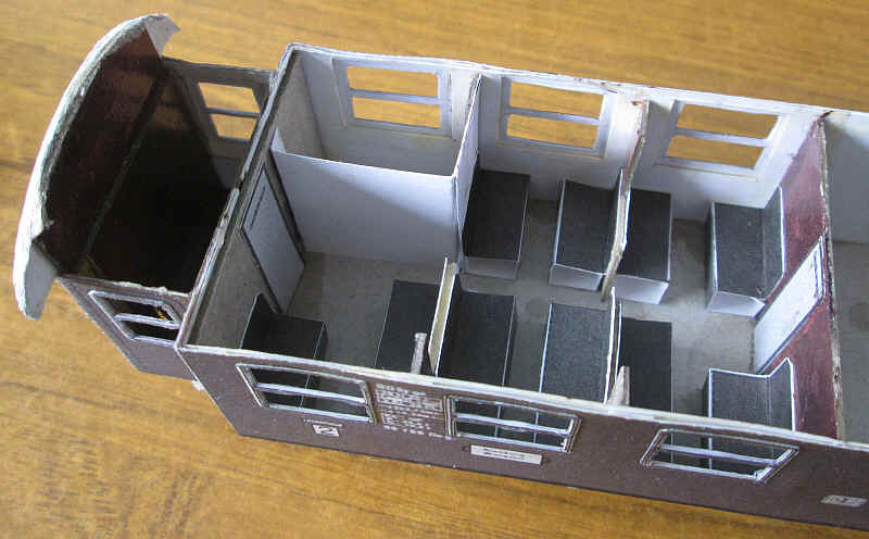
The kit comes with parts for the interior - this shows the toilet cubicle and the mixture of bench type seats - either for 2 or 3 passengers. The seats are simply folded up and glued in place
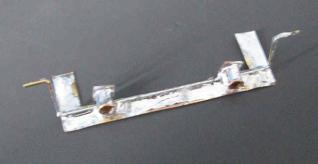
The method I decided on for attaching the buffers and footsteps was to cut a U shaped piece of brass to which some brass buffer housings were soldered and a length of wire to support the top steps. Initially, I'd intended to use this to form the support for the other steps but as construction proceeded I thought of a better solution and removed this length of wire.
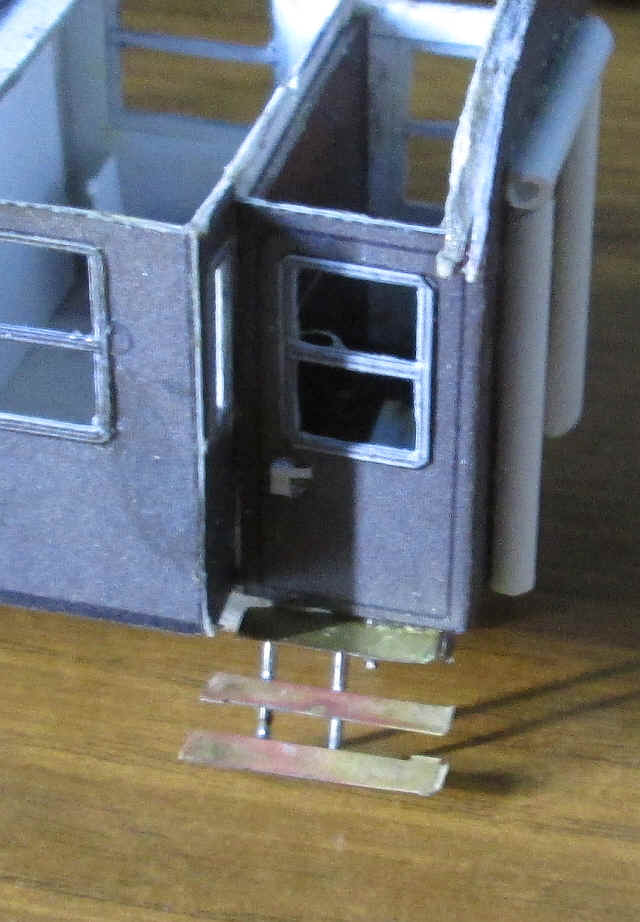
Two pieces of brass wire were bent at an obtuse angle and were pushed into holes drilled horizontally into the underframe and also soldered to the underside of the top step. This gives a very firm support for the middle and lower steps which were simply butt soldered onto the wire.
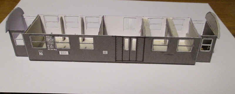
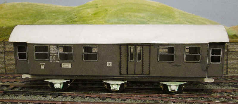
The model has now reached the stage where it will be painted.
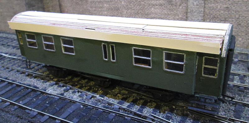
The body and chassis was sprayed with cans of grey primer and the chassis and steps with matt black. The body was then brush painted with Humbrol 195 satin. This is the recommended paint that is closest to the DB's chromodioydgrun. The window frames were initial coloured with a silver gel pen but this was then replaced with a metallic silver using a pen from Pilot. The interior is painted in the correct colours of cream and reddish brown.
Clear plastic strips were cut for the windows and slid in place for the windows along the sides. At the ends the glazing is held in place with a smearing of epoxy resin in the window recess. I had also decided that I needed some reinforcement of the card at the top of the sides as the thin cardboard was showing some signs of bowing in. I cut a piece of 1mm thick card to fit tightly inside the top of the body and glued this in place using epoxy on the top of the various internal cross pieces.

I was now on the third attempt to produce a convincing roof. The eagle eyed will have spotted that the appearance of the coach in the two photos above is slightly different. I had secured the unsuccessful roof to the body with epoxy resin so after removing this I needed to replace the ends of the coach and the internal brace ceiling. Fortunately, the body wasn't dameged in the process!
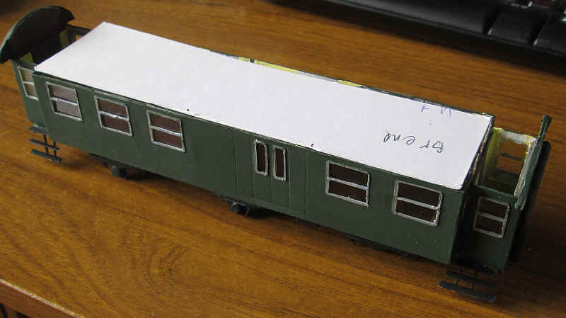
The pdf kit has tabs along the top of the body sides. I'd removed these as I intended to have a detachable roof.
However, with this attempt I've glued a tab along the entire body top and also added tiered layers of card to form a firm support for the roof.
Success on the fourth attempt! The roof was cut from the template on the pdf and slightly narrowed by about 2mm and then curved around a broom handle. One edge of the roof was glued to the side tab on one side of the model. After this had thoroughly set the underside of the card was coated with a layer of expoy and some was also run along the other side tab. Then the roof was pressed down and held in place with elastic bands until the epoxy started to set and then the edge of the roof was pressed firmly onto the tab until this hardened completely. A sliver of card then had to be cut from the edge to give a close fit to the side.
Here the roof is painted and the waterslide S Scale transfers have been added. These were made specially for me by Andreas Nothaft at http://www.modellbahndecals.de. I've only used a fraction of the lettering on the sheet. All that is left to do now is varnish the sides with matt varnish and add one or two small details such as the tail lights and the ventilation ducts at the passenger compartment ends.
Then of course there is the matter of building another three vehicles to make up a typical four coach rake.
The remaining three coaches
One aspect of the first coach that I was really unhappy with was the roof. I felt there had to be a better way which would avoid some of the problems that I'd had. My aim was to make the roof removable if necessary.
The method I finally adopted was:
Cut a base of thick mounting card 196mm by 44 mm to fit snuggly between the ends of the coach.
Cut a piece of thin card 202mm long (this is the overall length of the body).
From this mark out a piece 96mm wide and then draw lines along the length of the card 20mm from the edges. Score these with a biro and fold.
Mark in the roof weld seams with a scored line about 15-16mm apart.
Shape the 56mm wide centre part of the card to form a curve. I used my fingers and thumb to do this.
Trim the ends of the 20mm wide flaps so that they are the same length as the baseplate. This means removing 3mm from each flap at both ends.
Glue one of the 20mm flaps on the underside of the mounting card base ensuring that there the roof overlaps 3mm at each end and leave to dry.
Repeat the process with the other flap.
Place the roof in place on the coach body and check that all fits without gaps.
The roof needs strengthening so cut another piece of thin card to the length of the base. Form a curve with the fingers and apply a layer of epoxy resin to the top surface.
Slide this card under the outer roof and hold and press into place until the adhesive is set.
After checking again for fit the interior of the roof is filled with strips of mounting card glued in place. Start with a vertical piece along the centre line and then fill with strips of reducing width. These should be placed so that they are in contact with the inside of the roof and will form a very solid structure.
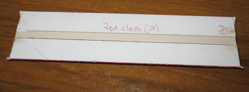
The photos below show different stages of construction
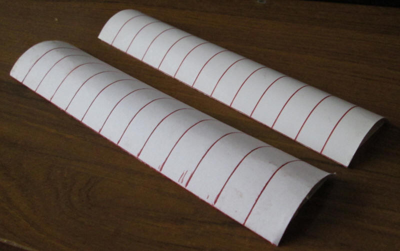
Note that the top surface of the roof overlaps the base by 3mm at either end. This will then sit on top of the body ends.
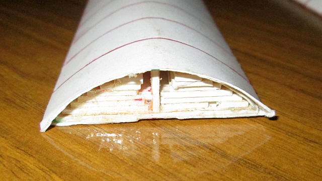
The end view shows the tiered strips that were inserted inside the roof to provide additional support to the outer skin.
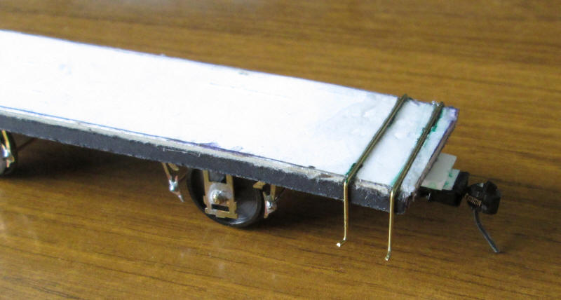
In another variation to the construction I decided to mount the steps in a different way. Two slots were cut in the top of the card chassis witha razor saw and 7thou brass rod was cut and bent as shown in the photo. The rod was then secured in the slots so that they are level with the top of the chassis.
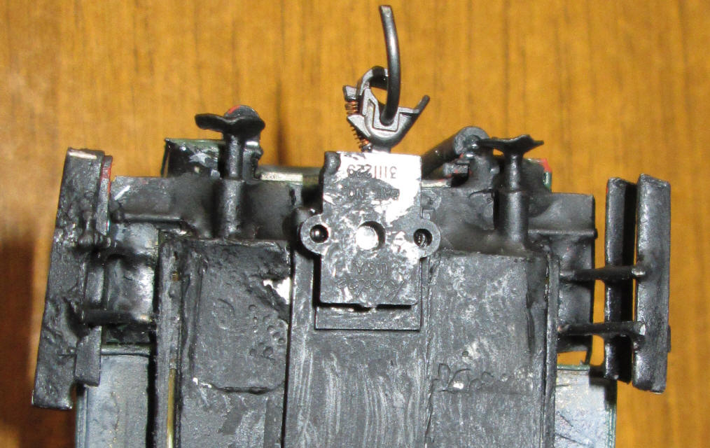
Another change that I've made is how the buffers are constructed. For the buffer housing I cut a length of 1/8th inch brass tubing about 10mm long. Then I drill a hole in the end of the chassis and push about the tube in about half way and secure with epoxy resin. The buffer head is a disc of tinplate punched out with a two hole paper punch. This is soldered to a flat headed nail that can be slid into the hole of the brass tube. I found some suitable ones that were intended to go with a very small plastic cable tie. The buffer head needs to be level with the front edge of the corridor connection. The brutally enlarged image shows that the buffer heads aren't actually perfectly flat but in reality this isn't in the least noticeable on the model itself.
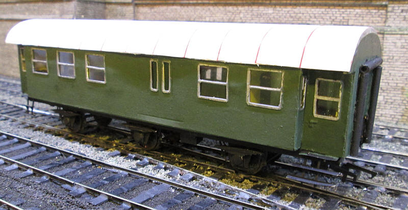
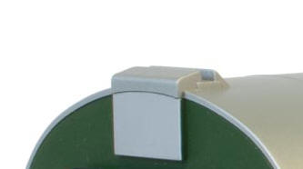
The final two steps in construction were adding the roof ventilators and the entrance door handles.
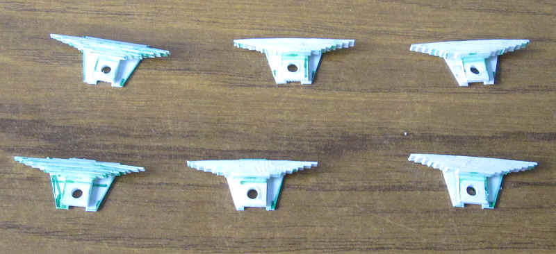
All vehicles have a strange ventilating system on the roofs which feed air into the upper part of the interior through flaps which can be opened or closed by the railway satff as needed. These were built out of laminated card cut at various angles to replicate the original. The photo below shows these as modelled on Lenz O Gauge models.
The first class class vehicles have an additional ventialtor which I made from a length of platic tube split down the middle with the sloping ends represented by a little epoxy resin.
The handrails were cut from nickel silver wire bent and threaded through holes drilled in body recesses near the doors.
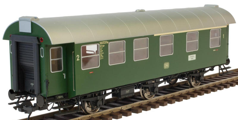
The photo above shows the Lenz O gauge model. My model clearly doesn't come anywhere near that level of quality. However mine costs about £15 for parts compared to over £200.