LMS Coaches
Suburban coaches
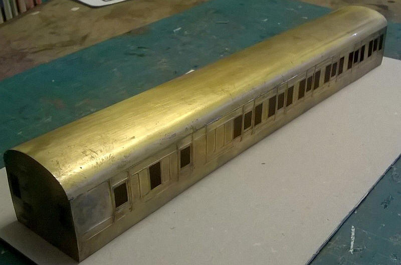
Having obtained two LMS Period 2 suburban coach kits that have been partly assembled I've now started work on them. The etched brass sides are very flimsy so I've decided on a slightly unusual method of construction.
The ends had already had the steps and the mounting plates to fix the floor in place soldered together. The sides were then soldered to the ends and the roof was tack soldered to the ends and sides. Once happy with the fit solder was flooded along the inside of the joint between the top of the sides and the edges of the roof. This results in a much stronger body at the top.
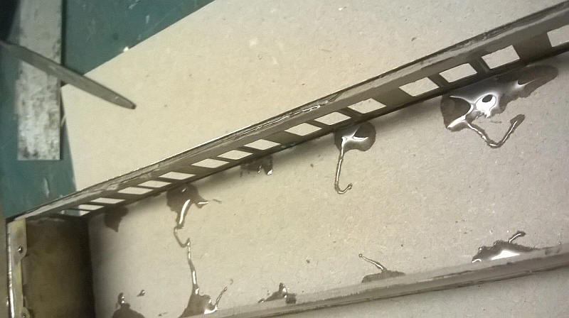
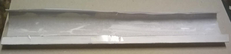
However, the lower edges of the body were showing signs of not being absolutely flat so the next stage was to strengthen the insides of the lower body side where the "tumble home" curve is. A length of 1mm thick card about 8mm wide was glued with epoxy to the inside of the sides positioning the card so the metal floor will sit on top of the card strip but in between the brass sides.
Also visible in the photo above (looking up into the body) is the false ceiling that has been glued in place. The epoxy has been allowed to run down between the edge of the card and the brass. The next stage will show why I decided to have a ceiling.
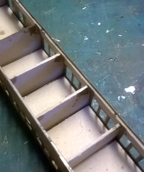
Another view looking up into the body towards the ceiling.
The compartment walls have been added and are fixed to the false ceiling and also to the card strengthening strips on the body sides. A rectangle of card has been glued to the ceiling of each compartment with a small gap behind the windows. This will be used to trap the glazing. The seats will be added after the model is painted and the glazing in place.
The aluminum carriage floor is now in place. The coach under frames will be built directly on this.
Building a carriage from paper and cardboard
If I am going to build some more LMS carriages I will need a way of producing the roofs. Building on my experiences with Midland coaches I've decided to try to find a way to mass produce them using paper and cardboard.
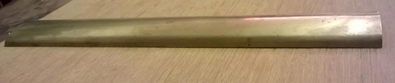
The two metal carriages I have come with an etched brass roof which had already been curved to the correct profile. I decide to use this as a former.
The first step is to cut a piece of A4 printer paper to the correct length and about 20 mm wider than the curved distance around the roof. It is then wrapped round the brass roof with flaps overlapping the edge of the brass roof. They are temporarily secured to the underneath of the brass with sellotape. These flaps will be used to secure the roof in place later.
The paper is then coated with a thin layer of epoxy resin adhesive and a second layer attached and left until the epoxy has hardened. The paper will require gentle pressure to ensure it is fully attached to the first layer of paper. It's also important to make certain that there is a sharp fold at the edge of the roof. Once dry the brass roof can be carefully slid out from under the paper.
The epoxy resin will ensure that the paper retains its correct shape. A length of thick (1mm) card is cut to the correct width for the base of the roof but a few millimetres shorter than the roof itself to allow for the ends of the carriage body. The paper roof can then be stuck to the card using the flaps
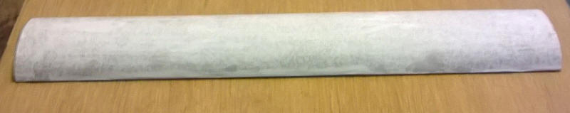
A third layer of paper is added and this is the resulting roof which is surprisingly rigid.
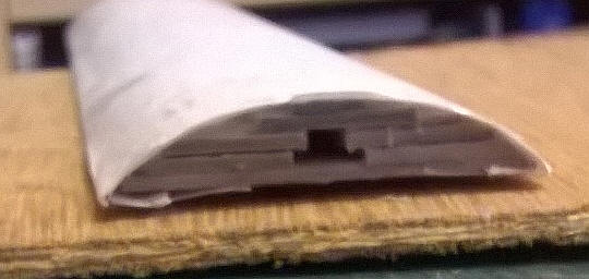
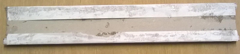
However, to strengthen it further more strips of card were glued in place under the roof. The outer edges were filed to an angle of about 30 degrees and adhesive applied along this edge. The photo shows the stepped layers with a final layer running along the centre line of the roof to give a firm support for the roof ventilators.
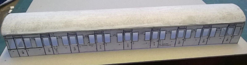
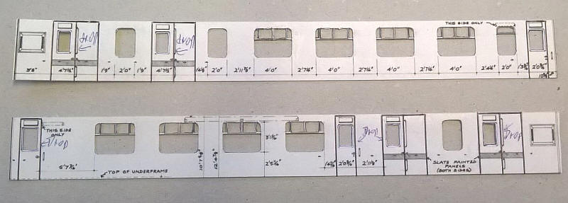
The book "Historic Carriage Drawings Volume 2 LMS and Constituents" contains large numbers of 4mm scale drawings. To complete a rake of three suburban coaches I'd need a composite but I decided to model a Period 3 coach rather than a paneled Period 2 to like the two brass coaches I had in kit form. The Period 3 one is also flush sided so will be easier to build and will be a good model to test techniques for the Stanier express coaches I will need.
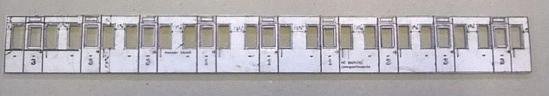
The photo above shows the completed side. The sides were printed out on thin card and the full sized door window openings cut out. Then a strip of printer paper was glued behind the window area. The compartment and door droplight windows were then cut out.
Two long strips of mounting board ( one 3mm wide and the other 10mm wide) were cut to length and glued above and below the windows respectively. This give the sides rigidity and will also give space for the glazing strips.
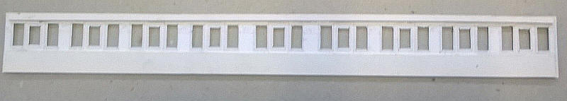
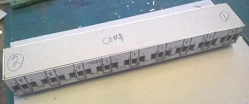
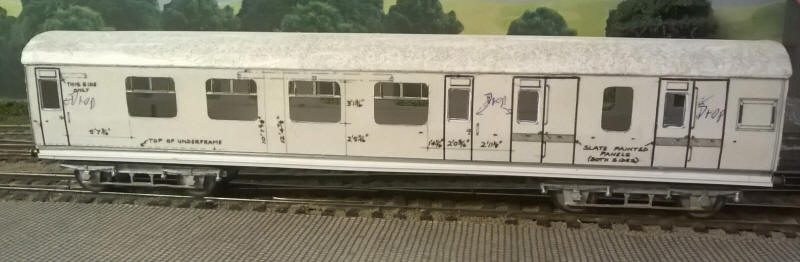
A 15mm wide strip of card was glued to the bottom of the roof to give a firm locating point for the top of the sides. The sides were then glued in place with contact adhesive to give a result...
...as seen here.
To strengthen the sides further compartment walls were cut from mounting card to fit tightly against the sides and false roof ceiling. Notches were cut around where the longitudinal strengthening strips of card were located.
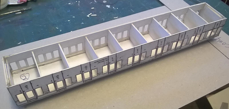
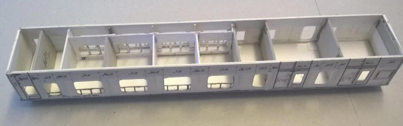
The completed body shell. Just visible is the narrow strip of the card that has been added to the upper strengthening strip of card just above the windows. This will trap the glazing at the top requiring just a few dots of adhesive to be need at the bottom of the window. At each end of the vehicle there are two strips of mounting board glued to the inner side of the ends. These will act as supports for the coach floor/ chassis unit.
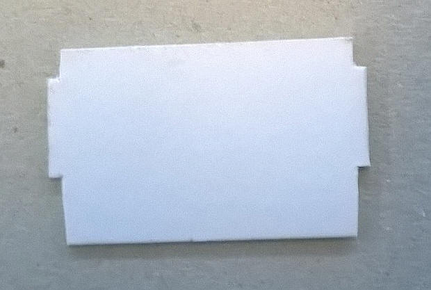
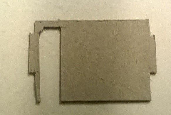
A piece of thick grey mounting has been cut to fit tightly inside the body. The chassis will be built on this in the same way as I did on the aluminum floor of the metal coaches.
Corridor coaches
I had expected that producing the sides for the Period 3 Stanier corridor coaches would be much more difficult than the suburban coaches. However this proved not to be the case. The corridor coaches all have distinctive rounded corners to the windows. I reduced these by making 3 or 4 cuts with the sharp point of a scalpel blade. The opening compartment windows were also quite easy to do. The sharp point of an old pair of compasses was used to make pin pricks at the corner of each opening. Careful work with the scalpel is needed but eventually all the windows were opened up. After cutting out each windows I coated the rear of the windows frames with superglue. This soaks in to the card and also forms a hard surface of glue on the rear of the frame. The result is almost as strong as etched brass. A sharp biro point was drawn around all the door openings before assembly began.
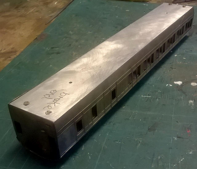
Construction of the body then followed the methods described above for the non-corridor stock with the exception of the compartment walls in the passenger are of this brake 2nd coach.
For these compartment walls I cut partitions with space for the corridor passage. I left some card to give additional support to the carriage wall on the compartment side. This won't be visible from outside once completed.
The main body is now complete with the various compartment walls in place. I've also added the doors and windows between the corridor and the compartments.
Bogies
The bogies for both the suburban and corridor coaches are more or less the same so I am batch building 8 bogies using a simple method I used for some of the Midland Railway suburban coaches.
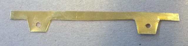
A basic outline was drawn on paper, photocopied multiple times and stuck onto some brass sheet. The axles holes were drilled and opened up to allow bearings to be inserted. The brass was cut roughley to shape as seen here using sharp scissors. The slight inaccuracies are hardly noticeable once on the track. I'm building models to operate not for a display case.
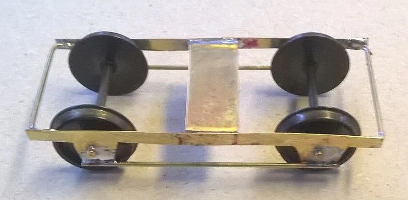
The first bogie has been soldered together. 1mm brass wire has been soldered across the space between the bearing holes. A 10mm wide strip of brass has been folded at each end to give tabs which are then soldered to the bogie side frames. The wheels have been inserted and 1mm brass wire soldered across the ends of the frame.
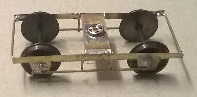
The stretcher bar has now had a hole drilled in it to accept the female part of the press stud which will form the pivot for the bogie. Small lengths of 1mm diameter wire have been soldered in placeto represent the secondary suspension of the bogie.
The underframe
Attention now turned to the underframe of the carriages. These will be made in a similar way to the metal bodied carriages using card and plastic.
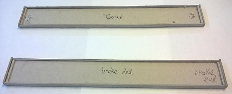
As I am building at least 7 vehicles it seems logical to list the dimensions of the parts for future reference. All card parts were cut from 2mm thick greyboard.
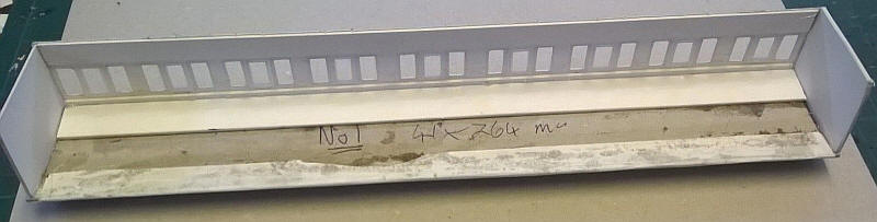
The first two basic underframes are seen above.
Buffer beams are 38mm by 5mm with 27mm biffer centres
The subfloor, which will be glued to the internal coach floor, is 265mm by 34mm. This gives a ledge 2mm wide on either side when glued to the internal floor.
The solebars are 265mm by 5mm and are glued on to the ledge referred to above.
Narrow strips of card are glued behind the bufferbeams to help ensure that the bufferbeams stay vertical.