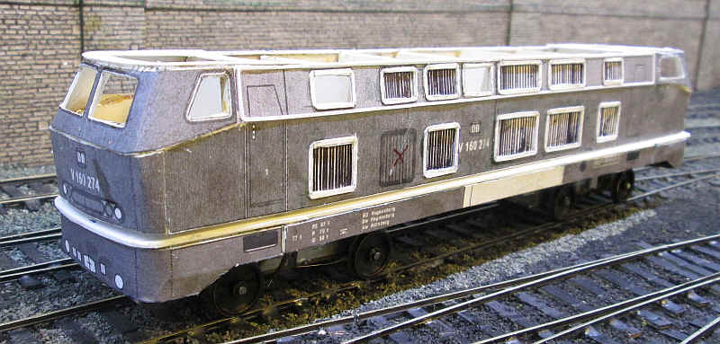
A DB V160 Bo-Bo diesel in S Scale
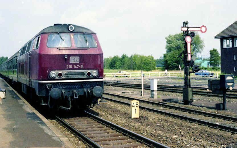
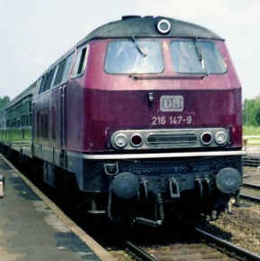
The various German mainline diesels of the V160 family are perhaps the archetypal Deutsche Bundesbahn diesel type. Utilising the same basic bodyshape there have been several variants of differing power and having different methods of train heating. They could, and still can, be found all over the country working everything from local passenger trains and freights through to top rank expresses.
Having already built a V100 diesel using the pdf card kits produced by Albrecht Pirling I decided to attempt the rather more complex V160 (later known as BR216).
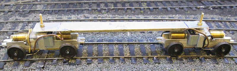
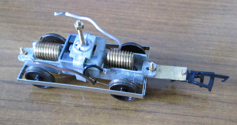
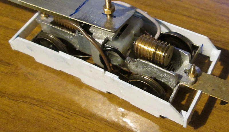
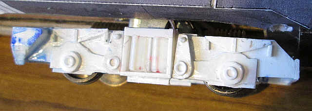
The power units for the models are BEC tramcar trucks (now produced by KW Trams) with a 42mm wheelbase which is virtually spot on for the V160. The trucks were supplied with O gauge axles and Ronford 14mm disc wheels which I then regauged to S Scale. A strip of scrap nickel silver was used as the chassis spine and the bogies were bolted in place as above.
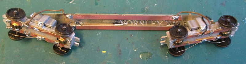
To strengthen the spine I soldered some double sided sleeper strip to the underside. These are also used to transfer power between the motor bogies giving eight wheel pick up. After a short running in period the chassis works smoothly with excellent slow running.
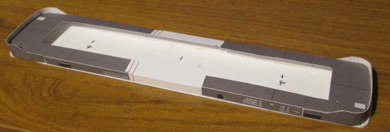
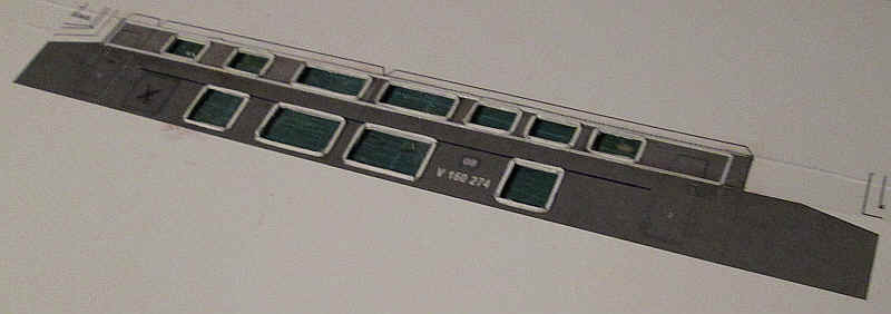
The pdf sheets were resized to S Scale in the same way as I did for the V100. These two parts are intended to be butt jointed and in my model will form the top of the chassis/ under frame unit.
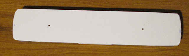
The card was then used as a template for a piece of 40 thou plasticard. This is being used rather than card as in its original livery the V160 had a very distinctive white band running all round the joint between the black painted under frame and the red of the loco's body.
The holes in the plastic are for the bogie pivot bolts.
By a fortunate coincidence the nickel silver spine of the chassis is at precisely the correct height to allow this piece of plastic to sit on top of it and maintain the scale height above the railhead for the white stripe
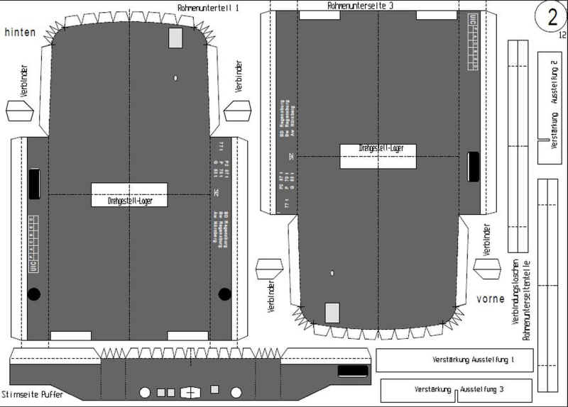
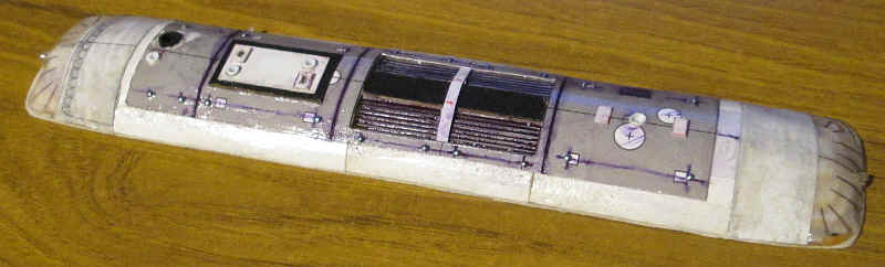
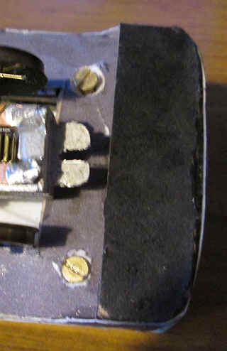
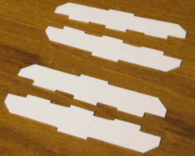
We now get to some cardboard engineering. The image above shows some of the parts for the under frame and bufferbeams.
These card parts have been modified slightly with the tabs folded over at the bottom of the white stripe rather than at the top. This is because they are then glued onto the 40 thou plastic.
I also cut away the centre section of the grey coloured card to allow the chassis to drop into place.
Because one of the pages of the pdf document I'd downloaded was missing the centre section of the under frame (the card in white above) was missing, so I simply cut one of the grey coloured pieces slightly longer so that it met its opposite counterpart.
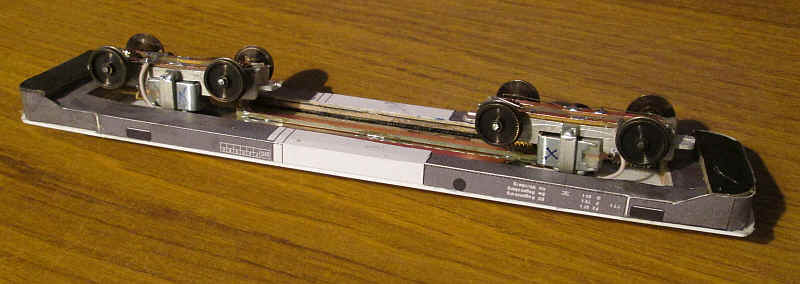
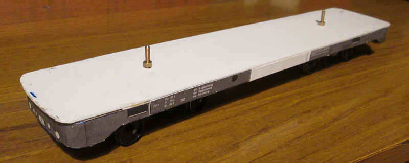
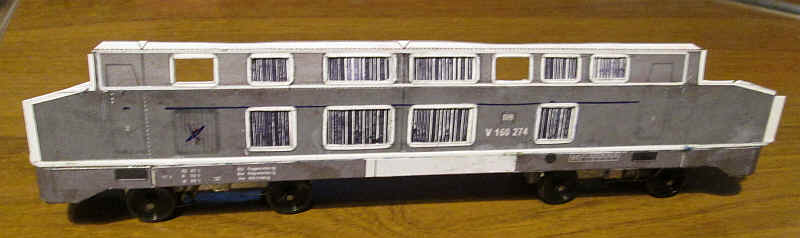
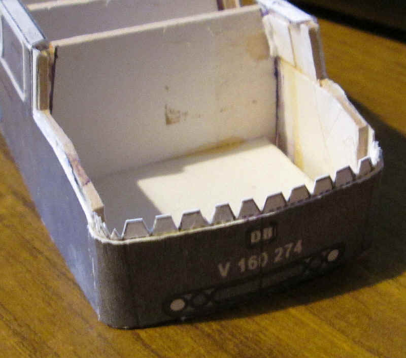
The two photos above so the chassis and under frame assembled. The parts, including the wrap around bufferbeams fitted together accurately with only a few miniscule gaps. Contact adhesive was used to glue the thin card to the plastic. Strips of thick card were then laminated inside the side frames and behind the bufferbeams with two part epoxy resin to produce a very solid under frame.
Building the body
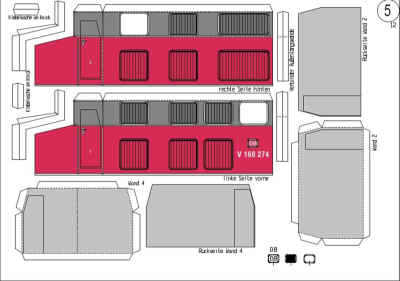
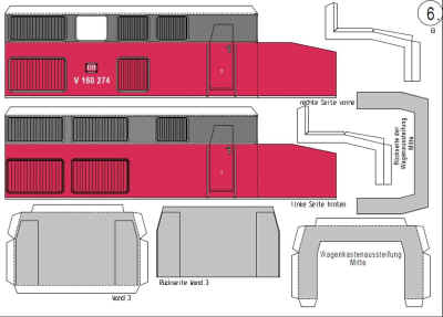
The parts for the body sides come in two halves as the kit is intend for O Scale so the sides wouldn't fit on a single side of A4 card. Having resized the pages to S Scale I decided to crop each bodyside half and then join them together using the 'create new panorama' function on my photo processing program. this would mean that the finished model wouldn't have a joint in the middle of the side. The resulting images are below.
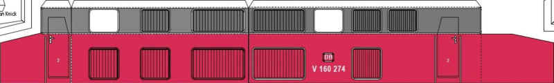
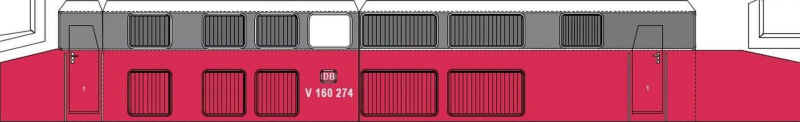
The sides of the V160 are not symmetrical and this is especially noticeable at the cab ends where the doors are not directly opposite each other. In addition the cab windows are different on each side.
The V160 kit isn't completely accurate as far as the placement of the bodyside windows and grills are concerned so I decided to correct this error by omitting one of the smaller grills on each side.
The stages in constructing the sides were:
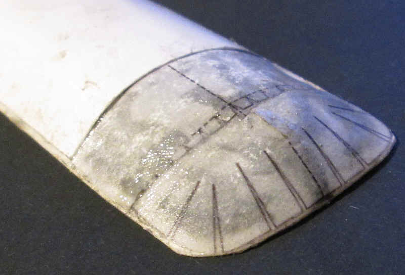
Using solvent secure microstrip around the part of the body that will when painted be coloured dark grey. On the real locos this is a shiny metal trim. The vertical ends of the trim were cut to give an impression of rounded ends. The side was then scored very lightly both above and below the microstrip and bent to form the upper bodyside tab and also the bend in the loco's bodyside.
Thin card rectangles were cut to form the beading around the openings for the grills and windows. These were trimmed and filed to give rounded corners on the outer corners. They were then stuck in place on top of the printed grills with PVA.
After the glue had dried pencil lines were drawn about 1mm from the edges of the card and the corners of the pencil lines were pierced with a compass point. The rectangle in the centre of the frame was cut out very carefully leaving a neat framework.
The completed body side can be seen above.
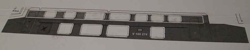
The next stage is to cut another piece of card that will be glued inside the outer side. This also has to be creased and folded inwards at the same place as that of the lower edge of the trim. The positions of the grills were marked and a biro was used to heavily score the card in the correct places to represent the vertical slats of the grills. Openings for the window glazing were also cut out of the backing card
This backing card was then glued behind the outer bodyside. It is also necessary to allow an overlap of this card at both ends to form the tabs to which the cab ends will be attached. Finally the backing card was scored along the lower edge of the bodyside and a tab about 15mm wide was bent backwards at 90 degrees to the side. This instantly makes the side more rigid and less likely to warp. The cab ends were bent slightly inwards to follow the tapering of the body at the ends.
With the two sides completed the two sides were joined together at the bottom with pieces of card glued onto the tabs at the bottom of the sides. What is essential is that the body is exactly the same width as the white plastic top of the chassis.
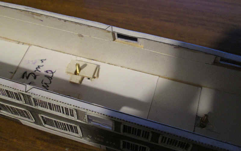
The body is fastened to the chassis with six 8BA bolts. The nuts are held captive with small pieces of thick cardboard with slots that prevent the nuts rotating or moving vertically. There are two fixing points in the centre of the loco's body and two under the cab floors.
Holes are drilled through the laminated card of the chassis for the bolts.
The lower part of the cab front was cut and bent to the correct shape. The ends had to be slightly trimmed where they joined onto the sides as otherwise the cab front stuck out too far. The tabs at the top of the lower cab front were an additional piece that is glued in place once satisfied with the fit.
The most demanding part of construction is the complex upper part of the cab which has to be bent in several planes. The first step was to cut out the window openings on the inner edge of the window frames. The small tabs along the top edge were cut and bent. These will later be used to fasten to the false roof of the cab. I found it necessary to trim the edges of the cab upper part to fit the main body sides. After folding the cab corners around a screwdriver I started gluing the cab from the front using the alignment marks at the front of the cab. Then it was a case of adding a little adhesive to the various tabs until the cab upper part was secured correctly.
Once all the cab parts were secure the whole of the inner surfaces of the cab were coated in two-part epoxy resin. This is essential to make the very thin pieces of card around the windows as strong as possible and will help prevent deforming. After the first layer had set hard a second layer was added.
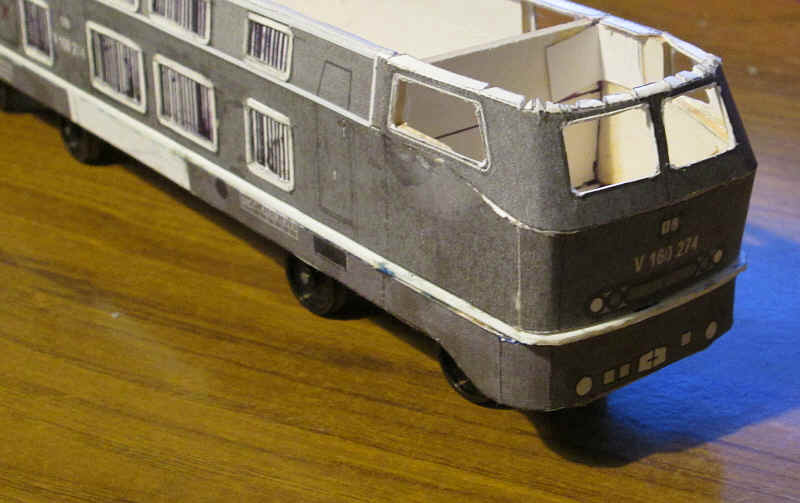
The photo above shows further progress. A cab floor has been added and the control desk folded up and fastened in place. The cab false roof has been fastened to the tabs along the top of the cabs - this was done using epoxy for maximum strength. The hole in the roof is to give access for a paint brush.
Also in view are the seven partitions that strengthen the main body shell and keep the sloping upper sides at the correct angle.
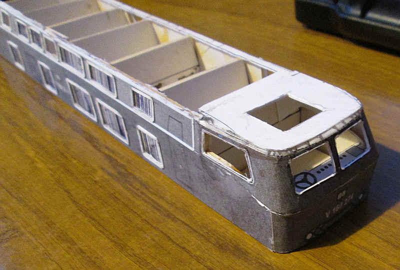
The other cab is now complete.
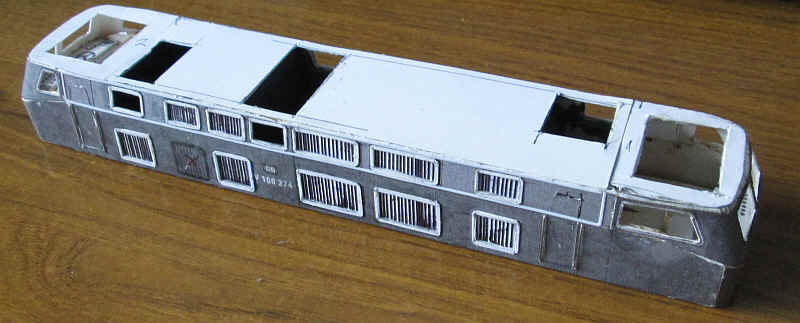
The door openings have been scribed with a craft knife and the cab handrails from nickel silver wire have been added. The sections of the body with window openings have been painted a dark grey. Finally the false roof with openings to allow the addition of the glazing after painting has been glued to the top of the body sides.
Building the roof unit
I felt that the least satisfactory part of the pdf kit was the roof. Photos of models built as intended showed a rather crude appearance with gaps and overlapping parts detracting from the final result. I decided that the roof would need to be constructed as separate part to the main body shell and that it would have to be much more substantial and where necessary the card would be filed to shape and any gaps filled with epoxy or other filler.
My first attempt at building the roof was, unfortunately not successful as it resulted in a roof that was about 2mm to high and completely distorted the appearance of the model. However, since this is a warts and all type of website I've decided to describe the first attempt. All the text for this unsuccessful section will be on a black background but please read it as many of the techniques I used were incorporated in the final roof.
|
The first step was to cut a piece of card to the shape of the top of the body. This would overlap the sides and ends by about half a millimetre and would represent the prominent rainstrip that runs around the base of the roof.
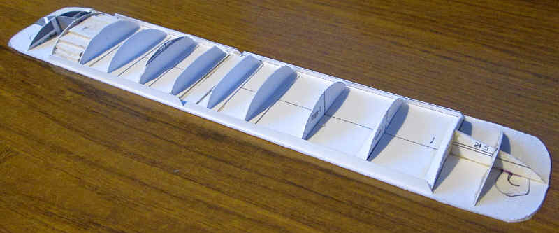
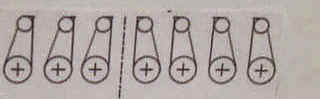
The kit includes a base for the ribs which will support the roof. These two parts are joined together and the tabs along the long side folded inwards. These will be used to fix the curved roof panels in place. The roof support ribs (Rippe) come in three varieties. Rippe 1 is for the main roof sections Rippe 2 is for the ends of the lowered roof section in the middle Rippe 3 is for the lowered roof section in the middle The small tabs on the curved section of the roofs were removed whilst the tabs at the base were folded over.
There are also some small ribs for the domed section of roof over the cabs.
These have interlocking slots which need to be cut out.
The photo above shows the assembled roof sub structure parts in place. Also visible at the far end are the first of the pieces of thick card which will be built up in layers to form a rigid sub structure onto which will be glued the various layers of the roof covering.
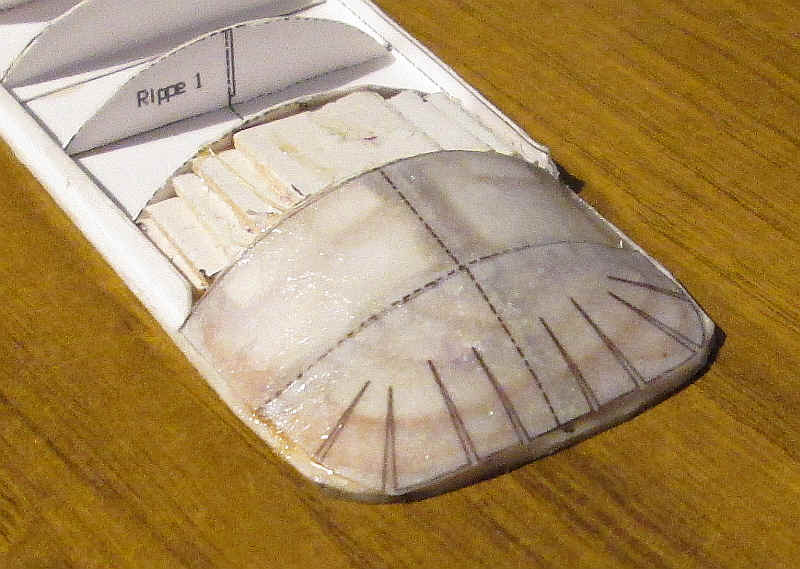
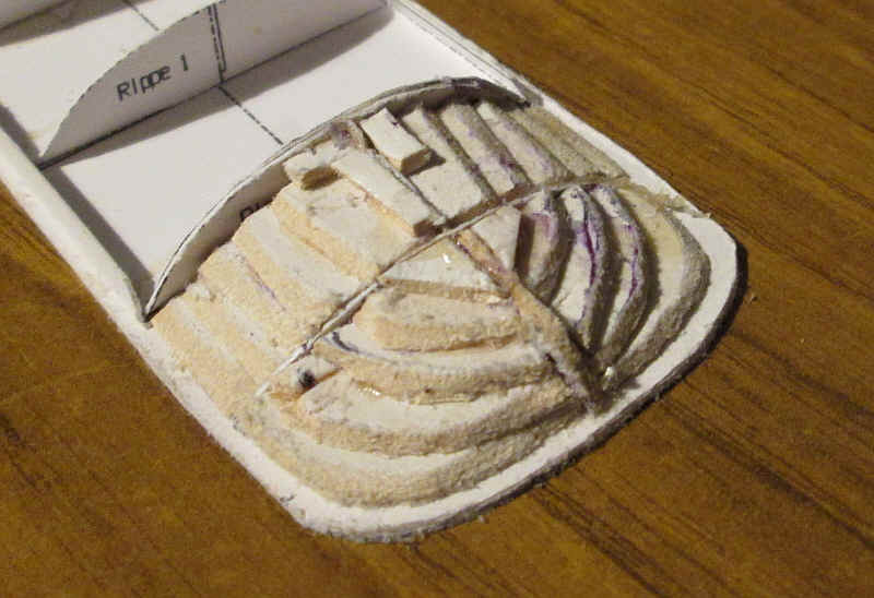
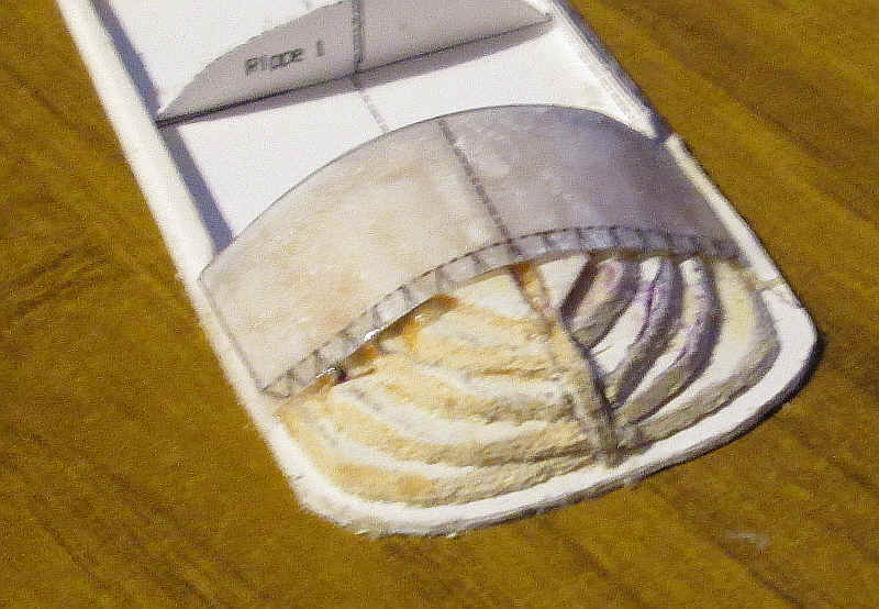
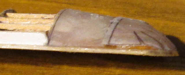
Constructing the domed end of the roof was something that has concerned me but in the end the method I used was remarkably simple. The photo above shows the completed roof end. How did this is described below. 4 The gaps between the ribs at the end of the roof were filled in with stepped layers of thick card tapered to a point at their out edges by filing the card. The two pieces for the domed end on the pdfs were printed out on printer copy paper and cut out.
There are two parts for the cab roof and I stuck these in place separately beginning with the "rectangular one" at the top of this image.
Then the stepped layers of card were covered with a thick layer of two part epoxy and the underside of the paper was also coat in epoxy. Then the paper was laid on top of the ribs and held in places until the epoxy started to harden.
Once this had completely hardened the curved part for the cab front was also glued in place again using large amounts of epoxy. Note that there was no need for the V slots to be cut as the paper will become slightly damp with the epoxy and stretches and easily adapts to a natural curved shape. The resulting roof is extremely strong as the epoxy sets and forms a solid base under the paper. In addition the top surface of the paper will have a thin film of epoxy on it from the carry over from the edges on your fingers!
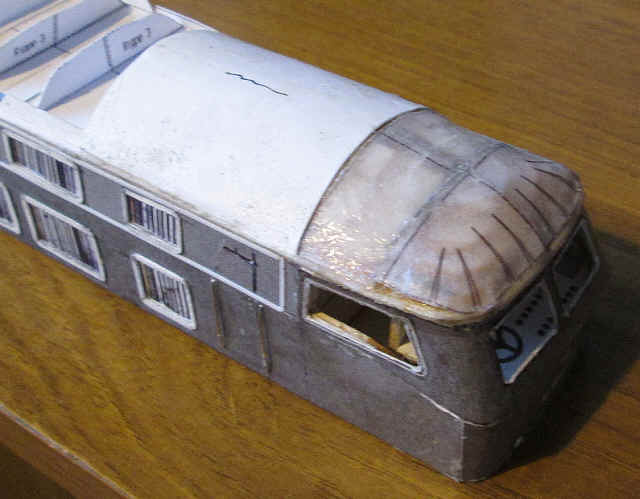
The first section of the main roof is now in place. After building the stepped card fillers between the ribs epoxy was applied to these and to the underside of the card roof section. This had been preformed to the correct curvature using screwdriver handles, paint brushes and fingers.
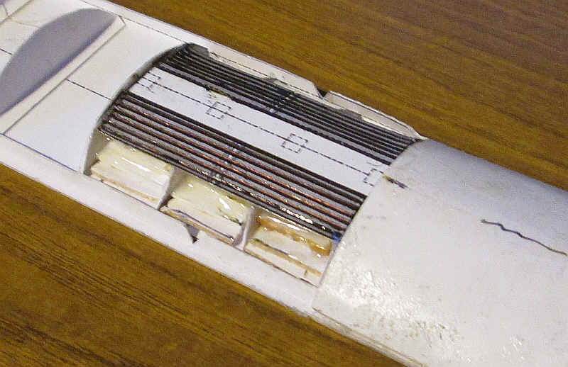
The next part to go onto the roof is the printed grills that are above the main engine compartment.
The lines were scored heavily with a biro before the rectangle was bent along the dashed lines and glued in place with a thick layer of epoxy resin.
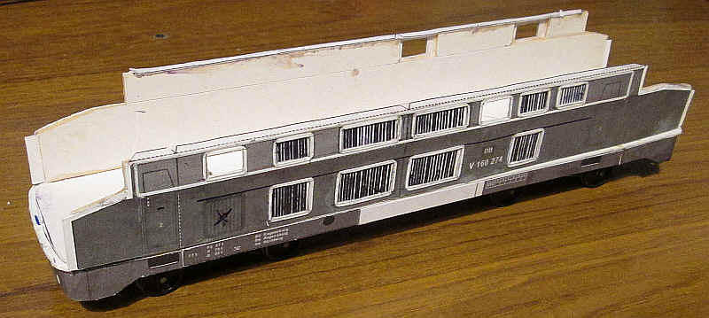
This photo unfortunately brought home to me that there was also a small but noticeable fault in the body shape. The top part of the body side should slope in more than it does.
What this meant was that I was going to have to very carefully remove all the internal partitions and the internal false roof. The use of a new knife blade and pliers to bend and remove the old partitions soon completed the destructive work with no disastrous results. New partitions were cut with much sharper angles on them and fastened in place. The body sides were obviously slightly weakened by this but several layers of card inside the body shell soon sorted out this problem and within a couple of hours the loco looked much more like the real V160 with its characteristic inward slope to the body.
The roof also had to be slightly narrowed to fit the revised body shell. Fortunately, I was simply able to file away the rather exaggerated rain strips on the edges of the roof which brought the roof down to about the correct width. The roof has also had a great deal of work done on it with plastic tubing inserted into the card roof to form the various exhaust outlets. The heads of small Lil dressmakers pins have been used to represent the lifting rings for the roof sections. The roof has now been coated with some Ronseal wet roof wood hardener liquid which makes the card really tough. I used this on my V100 with good results so I decided to repeat the progress on the V160.
|
The second attempt at the roof
Although I'd wasted a lot of time building the first roof most of the methods I used were repeated. The problem seems to have been that I hadn't made the necessary allowance for two things. Firstly, the base of the roof was too thick whilst the roof ribs (Rippe) when folded were lifted up by the thickness of the card tabs.
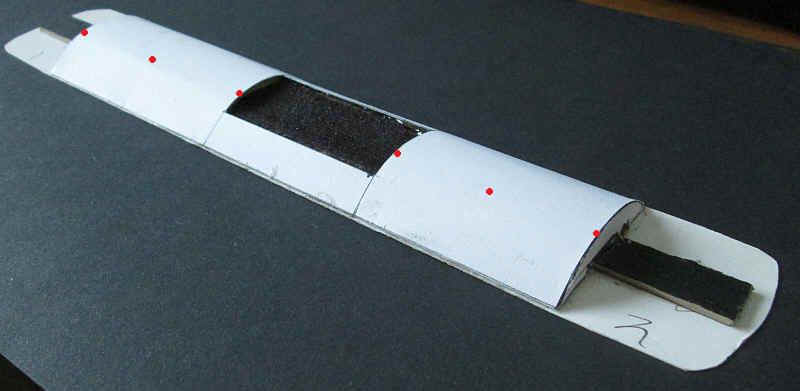
I made a template out of card showing the critical height dimensions of the locomotive and found that the height of the model up to the top of the body was absolutely correct so all that was necessary to ensure that the roof structure didn't exceed what it should be. A new base was made, this time out of thin card. A longitudinal spine of thick card (about 2mm thick and from an old Kodak photo paper box) was glued down the centre of the roof base as can be seen in the photo below.
Six roof ribs were cut from the pdf kit but reduced slightly in height by about half a millimetre. These were then glued on to the thick card and cut out. A slot was cut in the base of each rib to allow them to fit over the longitudinal spine and then these were glued in place at the points marked with red dots.
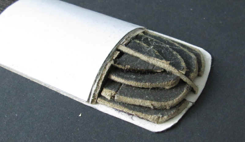
The spaces between the ribs were filled with layers of card gradually reduce in width towards the top of the roof structure, as I had done on the original roof. In the centre a new radiator panel was made as in the original roof. This time I decided to make the main section of the roof as one piece with the centre section cut out for the radiator grill section. After curving gently to shape the whole of the underside of this card was coated in epoxy resin, as were the layers of card. The roof was then placed in position and held in place with a few clothes pegs along the edges until the epoxy began to cure. Gentle finger pressure was then used until the roof was firmly held in place.
The roof ends were built in much the same way as in the first version, although using the scale drawing as a template has produced a better longitudinal profile. This sub structure was coated in epoxy and...
...and then the two pieces of paper printed out from the pdf were stuck in place. The first one to go down is the one next to the main roof and after that the curved front pieces is added. The joints between the various pieces of paper and card have been filled with epoxy and then filed smooth to give a flush surface.
The roof has now been completed with the various details as on the original roof although I have decided not to add the lifting brackets as these appeared too prominent.
Making the bogie side frames.
Work now moves on to the bogies. The first stage is to make up a basic framework using nickel silver strip that wraps around the motor bogie and is fastened to the white metal extensions using bolts. This method was also described in the V100's construction. Because of the distance of the bogies from the end of the body on the V160 an extension piece of brass sheet was soldered to this nickel silver framework and NEM coupling pocket bolted on to it at the correct location.
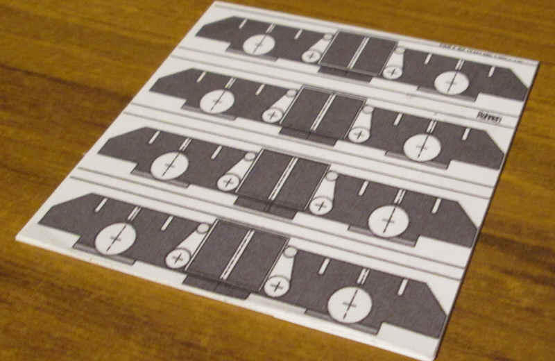
The cosmetic bogie sides are going to built up out of layered plasticard using the pdfs as templates. First I stuck paper print outs of the main frame sides to a sheet of 40 thou plasticard using small amounts of solvent along the edges.
Using the print outs as a guide the plastic was cut to produce 4 identical side frames. When finished the paper was peeled off the plastic.
The side frames were then stuck to the metal frame with epoxy resin. After the adhesive was cured I trapped the metal frame to the plastic side frame using slivers of plasticard. the ends of the side frames were joined with narrow strips of plastic and then reinforced with small lengths of square section plastic strip.
Part A
Part B
Part C
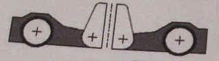
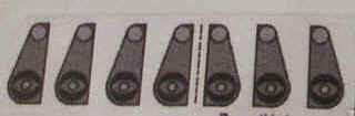
The suspension of the real V160 is quite complex but is represented quite neatly on the pdfs by the various pivoted levers and leaf springs. The three main parts are shown above.
The paper print outs are fastened to the plasticard with solvent and then carefully cut out. A coarse file was used to removed the paper from the plastic and then the various parts were secured in the correct position.
The two Part As are secured directly to the main side frames leaving a gap in the centre - this is where the two large primary suspension springs are located. The lever Part B is the fastened to A and finally Part C is added on top of B. This builds up to look like the substantial lump of metal it really is.
The photo above shows the almost complete bogie side frames. From left to right the rear sandbox is made from four layers of plasticard cut and filed to shape. These are very complex in shape and I built the card sandboxes form the pdf to help work out what to do. They are an amazing piece of graphic design which fold up accurately.
The springs and their various hangars are shaped plasticard and microstrip. The axle boxes are made from a punched disc of plastic with a sliver of plastic tube on top. The vertical levers have a sliver of tube for the lower larger hinge with the small top one being a length of micro rod secured in a drilled hole. The rectangular box shaped block in the middle is from various strips of plastic and holds two short lengths of biro tube which will be decorated to look like the primary suspension springs. Still to fit are the front sandboxes which have a very complex shape so I will wait for an inspired moment before shaping!
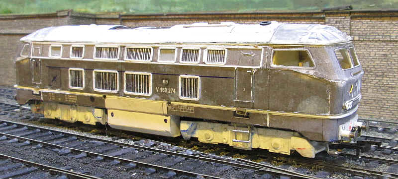
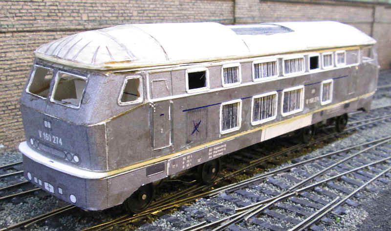
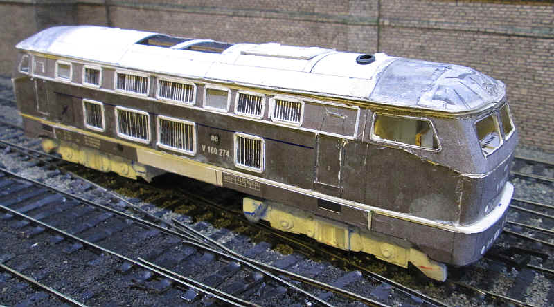
The two sides of the completed locomotive are seen here ready for painting
Construction has moved on to the detailing stage:
The front sand boxes have now been added.
Holes for the fuel points and cab steps have been cut in the under frame and on the edge of the white plasticard.
The fuel tanks and battery boxes have been added.
Cab steps have been soldered up from 0.9 mm brass wire and secured firmly into the layered card of the under frame with epoxy resin.
Buffers have been made using plastic tube for the shanks and Alan Gibson buffer heads with a disc of tinplate soldered on top.
Various handrails have been added to the cab front.
The air brake pipes, a coupling hook and the shunter's steps have been added to the front bufferbeam
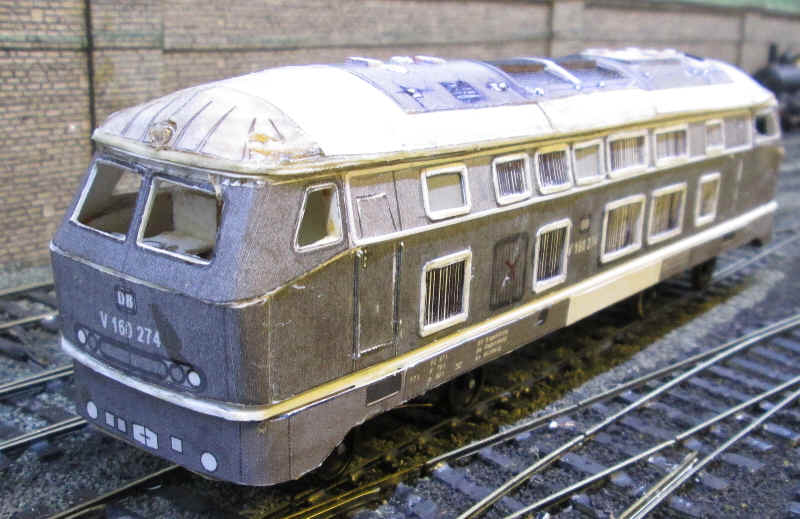
The locomotive has now been painted and lettered. Paints used were Humbrol 20 gloss maroon, 32 dark grey for the upper bodyside and underframe and 79 grey for the roof . The aluminium trim around the upper grills and between the lower bodysides and the underframe were coloured with a Pilot silver marker pen.
Transfers are from Andreas Nothaft http://www.modellbahndecals.de
These were made specially in S Scale for me and are resized versions of the HO Scale waterslide transfers. The cost for all the lettering needed for one locomotive was just under 7 Euros - amazingly cheap with delivery time being about a month, exactly as promised.
After painting and lettering the model was sprayed with Humbrol satin varnish which gives an almost matt finish.
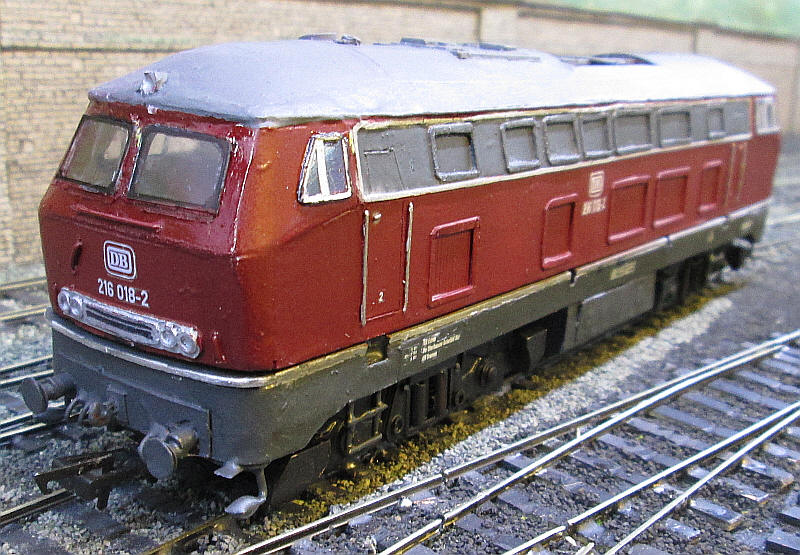
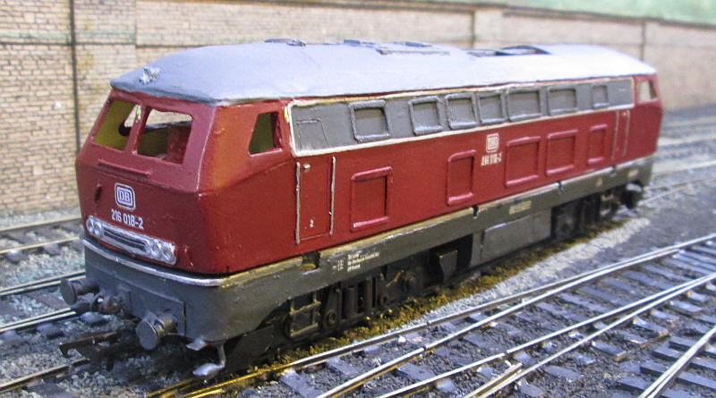
The windows have now been added to the cab sides and front. These proved much more difficult to apply compared to the V100 as the surfaces, esepcially the cab front are not totally flat and curve in different planes. However, after several failed attempts, the cab front windows were secured in place. They are simply made from clear plastiglaze with th "rubber" window frame added using a black overhead projector pen. The glazing was held in place with a layer of epoxy resin.
The side windows were made in the same way as those on the V100 with the paper window frame cut out from the pdf printed on paper. The frames were then coloured using a Pilot silver marker pen. These were stuck in place on to the glazing with PVA glue and then the edges were sealed with a smearing of epoxy. The final touch was to draw a black line around the outer edge of thje window frame top represent the rubber seal. They were then attached to the body with a epoxy.
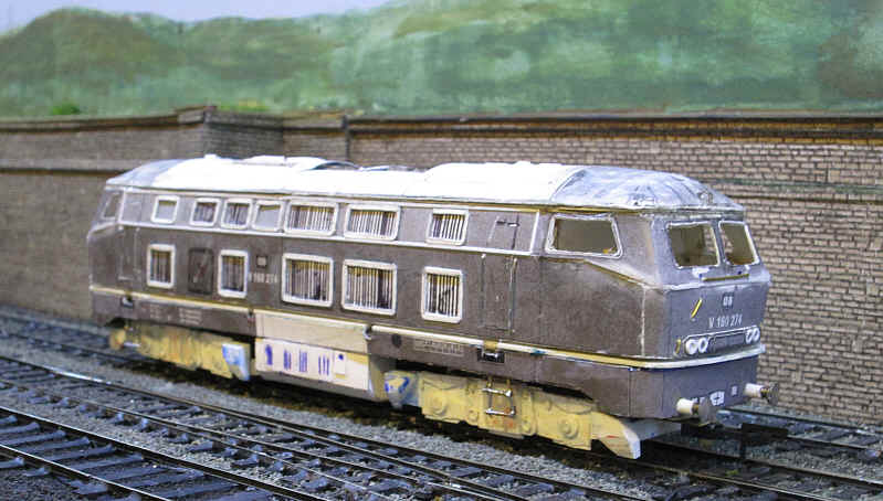
The model is now basically complete. The front of the cab needs a coat of satin varnish to blend in the the gloss paint that had to be applied after I'd had problems with the windows. The headlights need the correct colours applied and the windows on the engine room compartement need some glazing adding to the recesses.
This is certainly the most complex and difficult model I've completed and whilst there are numerous errors it does give the impression of a BR216 and that is what I set out to achieve.