Building a pre-war Deutsche Reichsbahn Eilzugwagen coach
It seems a logical step to build some pre-WW2 carriages for my German layout. Many of these vehicles were in service until the 1980s and on several occasions I found myself travelling in one.
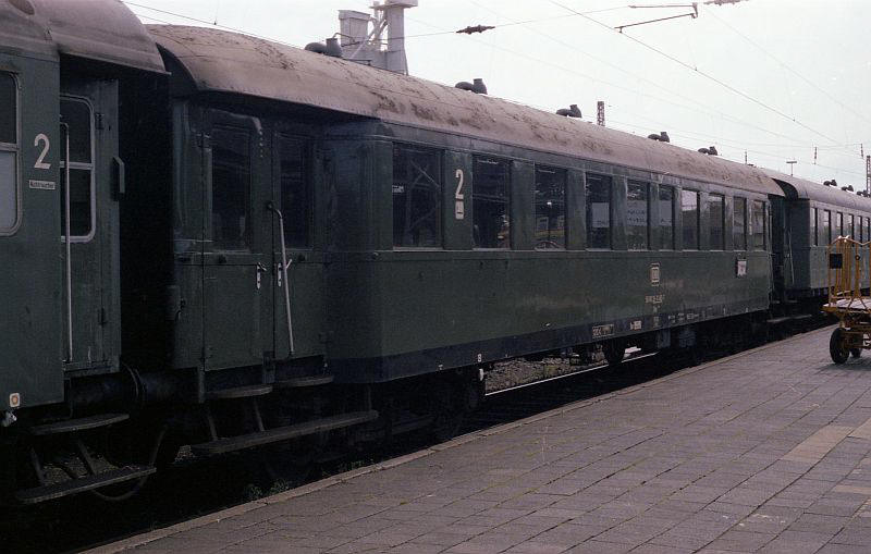
This is a type Byge667 which was built in the late 1930s and was included in the formation of a Norden to Wilhelmshaven local train in 1980. This type is interesting visually as two of the windows in the centre are spaced closer together than the rest of the windows.
There were several different types of various lengths whilst some had double doors and others single doors. Interiors also varied. with 2 plus 2 seating as well as 2 plus 3.
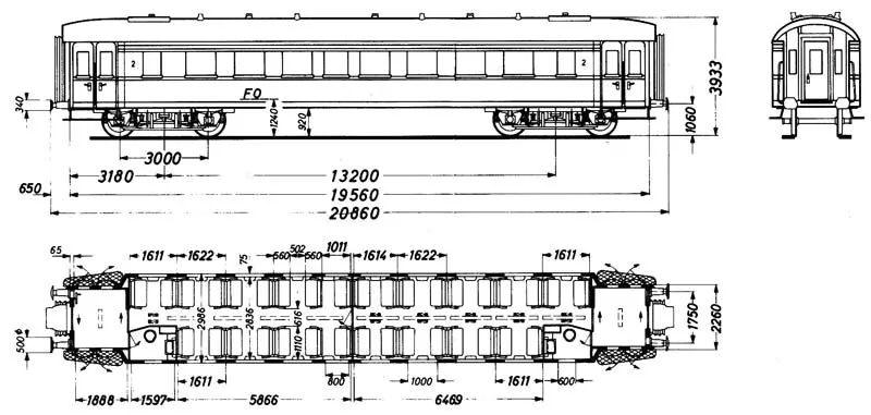
There are two types that I intend to build. The diagram below is of the Byge667. This has a slightly unusual appearance as two of the windows at the centre are spaced much closer together than the rest.
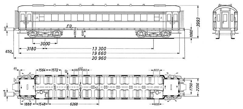
A slightly longer version is the Byge655 which has evenly spaced windows
Byge637
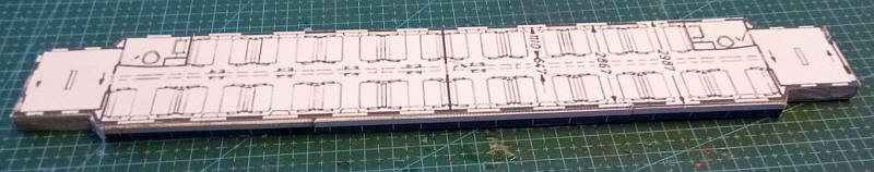
The coach base is made out of three layers of greyboard glued together and with the upper layer having the seat plan glued in place on the top.
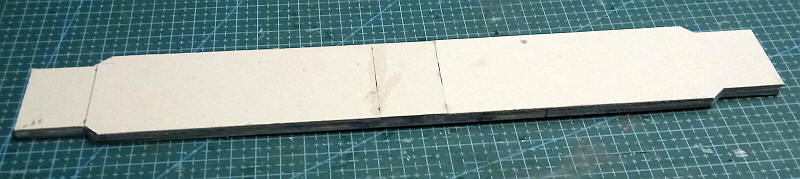
Unfortunately, in S Scale the ends and body sides are too long to fit on a single length of A4 card so they are made from three separate pieces of card.
The coach sides and recessed doors were printed out on 220 gsm card and then glued in place to the top edge of the base. The inward sloping body sides and door ends overlap and are glued together.
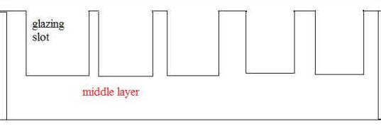
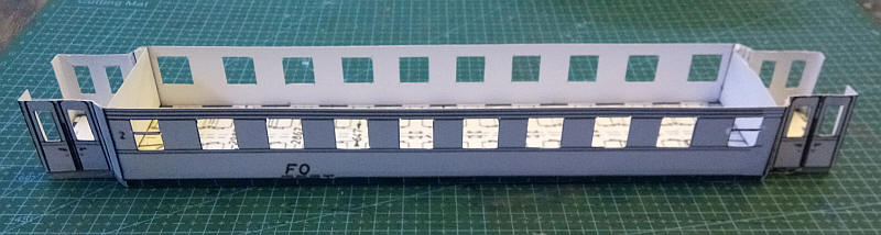
These pre-war coaches didn't have any cross walls to break up the interior so I've adopted a slightly different method of construction for the saloons compared to my other carriages. After cutting a layer of card in a comb-like shaped into which the glazing will slot (as above)......
.....the inner layer is made out of a strip of 2mm mounting board that fits along the inside of the saloon and has holes cut in it very slightly larger than the outer window. Both layers are glued to the outer wall of the carriage and now form a really rigid side. This will be made even stronger after the seats are added and the roof structure slotted in place.
The thin card needs considerable reinforcement especially at the ends so I've added an internal layer of 2mm thick mounting board on the inside of the vestibule ends. Space has been left behind the door windows for a piece of glazing strip to be added later.
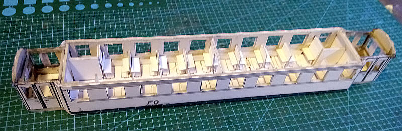
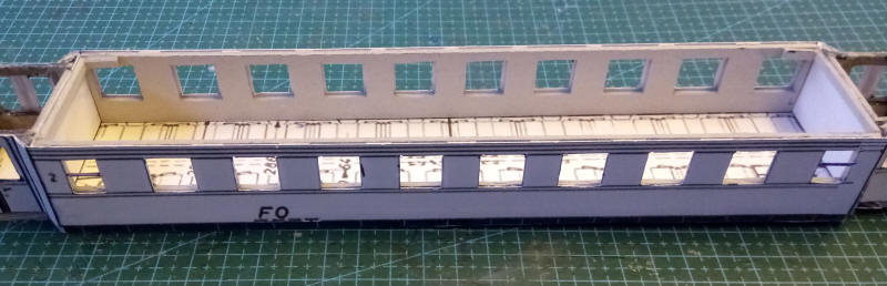
All the seats and toilet walls are now in place. The seat backs are out of strips of mounting board and thin card is used for the seats which are supported on more strips of mounting board.
The roof is built as a separate unit. The base is a 2mm thick piece of mounting board cut to fit tightly inside the ends of the carriage and about 2mm narrower than width of the body. On to this is glued a vertical central spine of mounting board which is cut to overlap the ends and provide support for the domed end of the roof. Layers of mounting board of reducing width are glued to the base to give support to the curved roof covering.
The central section of the roof is a layer of thin card coated on its underside with two part epoxy resin. The card is also wrapped around under the roof substructure and secured to its underside.
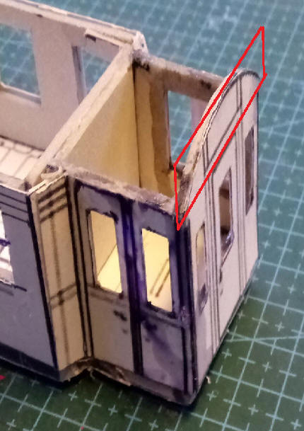
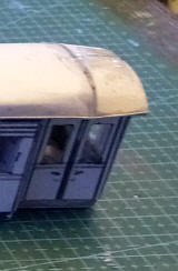
The domed ends were more complex to produce as I found it necessary to remove the curved top of the ends and glue this to the roof substructure, The section removed is inside the red outline.
The domed ends were made by curving and gluing two thin strips of card to the tapered ends of the roof sub base. These overlapped the ends and met in the centre line of the roof. As the epoxy sets the card was curved into shape with finger pressure. Any gaps were filled with epoxy.
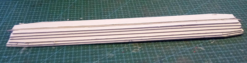
The rain strips along the length of the roof have been added as well as the strips across the roof using 10 thou microstrip.
The ventilators for the toilet are thick rectangles of card.
The gap between the end of the carriage and the curved end to the roof . This will be filled in after the roof is finally secured to the body.
I've used a different method to constructing the bogies making these as a one piece structure, rather in the manner of those found in some etched bogie kits.
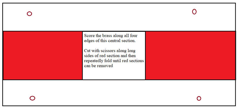
The bogie sides and the centre pivot stretcher are cut from one piece of brass sheet as in the diagram above. Holes for the bearings are drilled out and then a heavy duty knife is used to score the brass around the central pivot stretcher. The two rectangles (in red above) are then removed by first cutting along the long edges and then bending the brass repeatedly until they come loose. The bogie sides can then be folded along the scored lines to give the basic bogie frame. Top hat bearings are then fitted, the side frames are then trimmed roughly to the correct shape using scissors. After inserting the wheels the end stretcher bars (0.7" brass wire) are soldered in place.
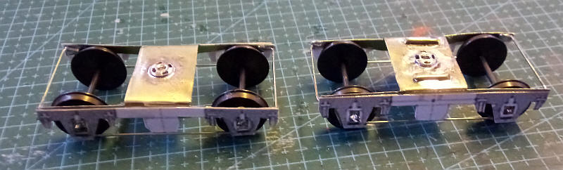
The two bogies with the basic frame overlays added from card. Details will be built up on these from different layers of card and wire. The press studs used as bogie pivots and the strips of brass wire used to prevent the body of the coach rocking can also be seen.
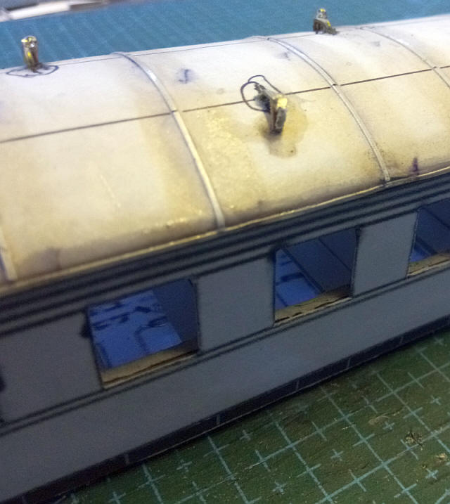
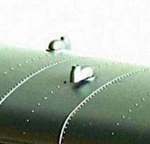
One of the problems I faced with this model was the roof ventilators. These were an unusual shape which is difficult to reproduce in model form. I've used 1mm diameter wire bent into a U shape with a short and long leg. The long leg goes into a hole drilled into the roof whilst the short leg just touches the curve of the roof. Another vertical length of brass is soldered to the short leg and this is then covered with some epoxy. The aim is for it to look something like the small image of the roof of a HO scale model.
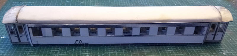
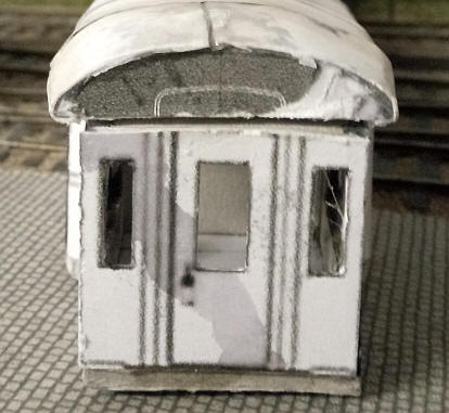
The buffers (BR heavy duty wagon white metal castings) and the end steps (from nickel silver wire and strip) have been added. A Hornby coupling has been added at one end and a Kadee at the other end. I intend to run the coach with either one or two bogie Umbauwagen which have Kadee couplings.
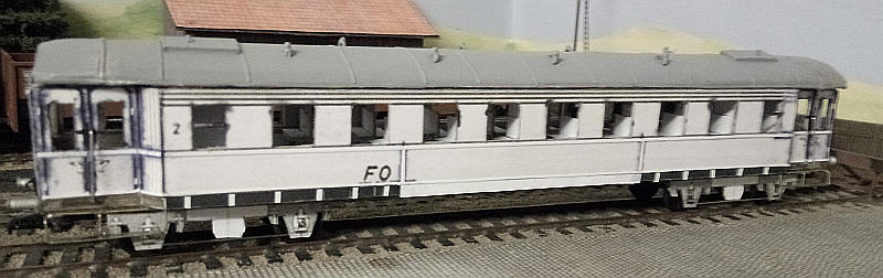
I've now added the long metal handrails at the doors as well as the various longitudinal and vertical beading strips that can be found on the coach sides.
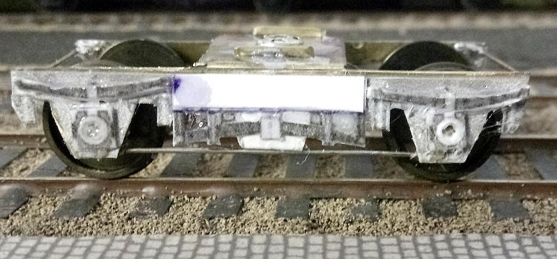
The detailing on the bogies is from the pdf kit and is simply a series of multiple layers of card to represent the springs and axleboxes.
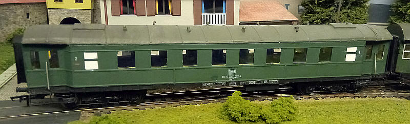
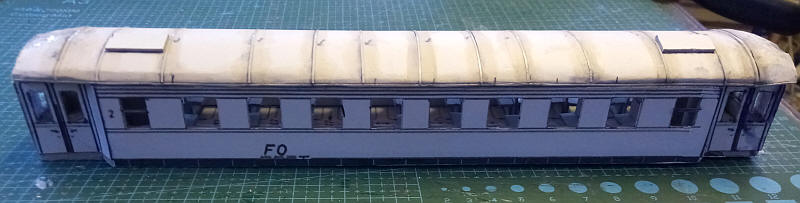
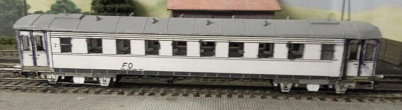
The completed model with corridor connections added and lettering as usual from Andreas Nothaft.