Building a BR 78 4-6-4T
Having already built two German tank locos for my Bavarian branch line it seems logical to build a model of the Prussian T18 which later became the BR78.
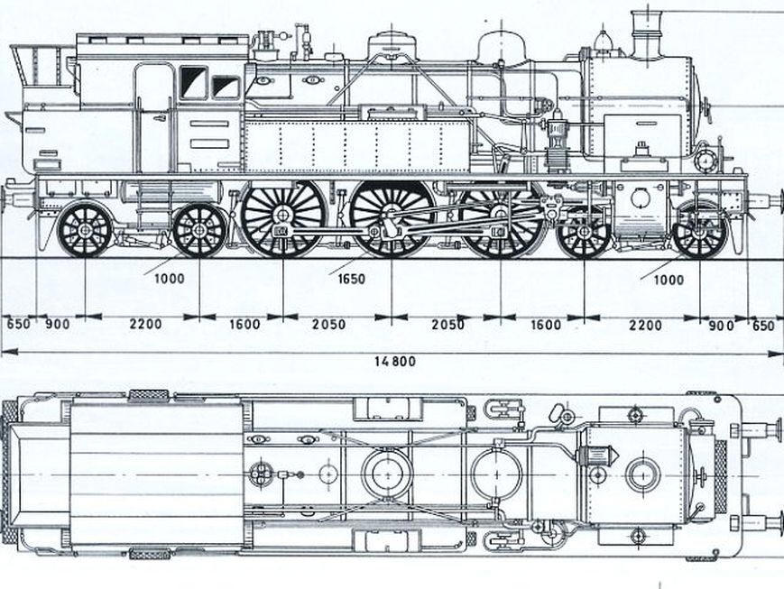
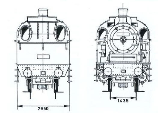
The starting point was these diagrams found on the Internet. They were resized to S Scale and printed out on card.

I only saw a few of the BR78s including 078.246 at Tübingen in 1971.
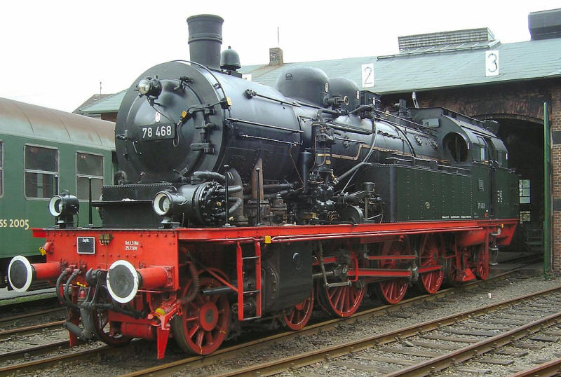
A much better image is this preserved example
(reproduced under Creative Commons: https://en.wikipedia.org/wiki/Prussian_T_18#/media/File:78_468_Dieringhausen.jpg)
Searching for suitable card kits of models of the BR78 I found one of the Polish version of the class which was designed for HO 1:97 scale. Many of the BR78s that had worked in the parts of Germany that became Poland after WW2 were absorbed into the fleet of the Polish railways The loco uses three sheets on the pdf.

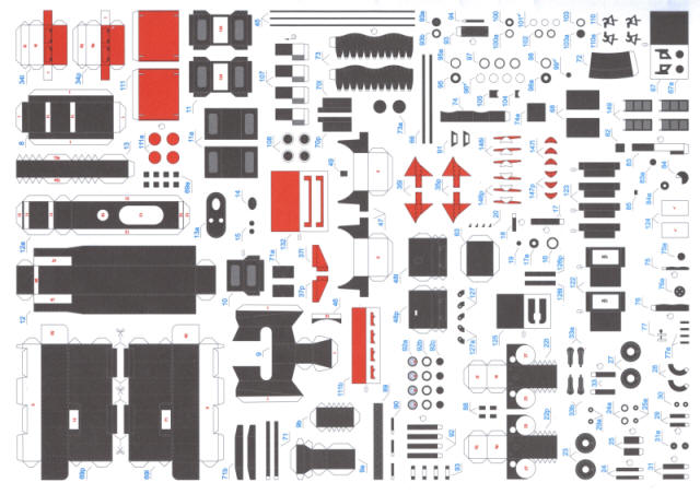
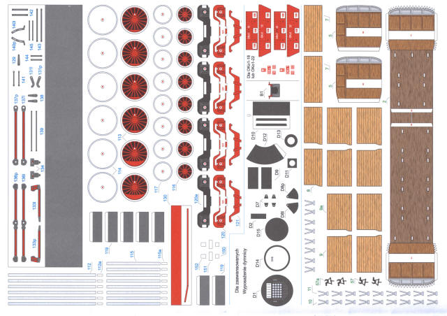
Rescaling the pdf to S Scale and comparing it with the outline diagram above shows that it is basically accurate so I will be using some parts as the basis of my BR78.
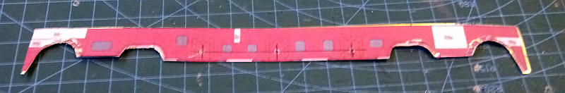
The frames were printed out and glued onto a sheet of 0.16" brass sheet cut carefully to the shape of the paper template with sharp scissors. Using a steel ruler to make sure the axles holes will be in a straight line, I used a sharp compass point to mark the centre point of each hole and then drilled through the brass to make a pilot hole.
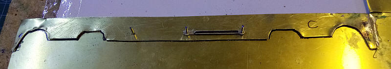
This shows the next stage. I've removed the paper template and tack soldered the frame side to another piece of brass which will later be marked out and cut to shape for the other frame side. The axle holes have been opened out to just the correct size for panel pins to be tapped into the piece of chipboard. After the heads of the pins have been removed these act as the jig to solder the coupling rods to the correct length. The rod that is already in place came from an old 4mm scale model which had precisely the correct spacing. The other rods will be made from spare Alan Gibson Crab rods.
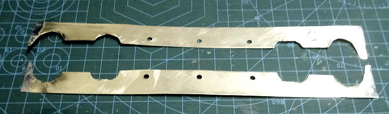
The frames have had the axle holes opened out to ready to accept top hat bearings.
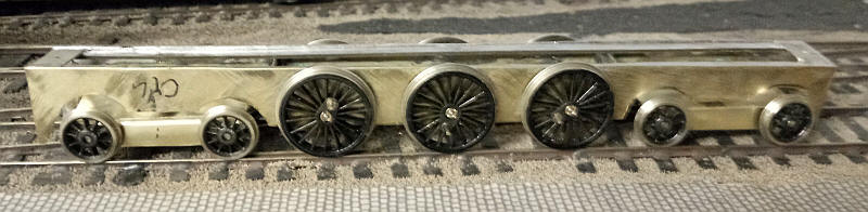
The frames have been assembled with my usual method of strengthening the thin brass by soldering double sided copperclad sleeper strip along the top edges. A small number of frame spacers have been added and the bogies have been assembled as below.
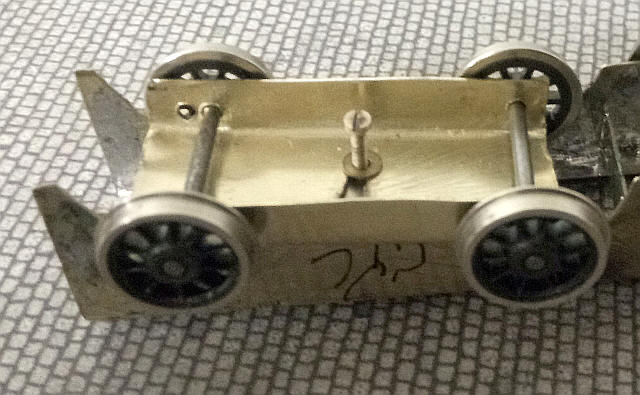
The bogies are made from one piece of sheet brass with axle holes drilled. The brass was heavily scored where the fold is to be made and bent to shape in a small vice. The pivot point is a slot about 5mm long through which a bolt is screwed into a nut soldered over one of the frame spacers. Thus the bogie frame can move from side to side as well as the axles having several millimetres of side play. This allows the chassis to roll smoothly around the 36" radius curves on the layout.

The chassis is now partially complete and is powered. The motor, wheels, brake gear and coupling rods have been fitted and the chassis runs smoothly down to about a scale walking pace. The Romford (Markits?) wheels are from an old 4mm scale LMS Class 5 and unlike my other S Scale locos are only insulated on one side meaning I only needed to fit one set of nickel silver pickup wires. Some minor modifications to the bogies have also been made - strips of brass have been soldered either side of the pivot slots that had been cut rather roughly through the brass. I've also soldered larger brass washers to the pivot bolt head and added some lead weights to the underside of the bogie frames. These changes allow the bogies to move from side more freely and hence no derailments.
The footplate will be a combination of card and metal. The first step is to cut a piece of card with holes to clear the top of the wheels. This has been coated with wood rot fluid to harden it.
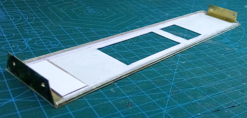
The buffer beams have been made out of some scrap etchings which had a right angle bend already etched into them - they came from some jigs used for assembling footplates that were included in some Alan Gibson loco kits. They were cut so size and holes drilled before attaching to the card with epoxy resin. The valances along the underside of the footplate is N scale laid on its side with the wider bottom edge facing outwards. A strip of thin card glued to the underside of the footplate was used to support the barrower head of the rail thus ensuring that the valances would appear to be vertical.
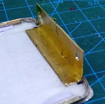
The front edges of the valances curve around to meet the front buffer bean. To do this I filed away the head of the rail leaving just a thin strip which was curved to match the curve on the top of the footplate. The valences were secured with more epoxy resin.
The footplate is placed in position- a little packing was necessary at the rear to get it to sit absolutely the same height at the front and rear. Obviously, at the moment the footplate assembly is not very strong but will become more rigid as construction proceeds.
The buffers and coupling bar have now been fitted as well as the nuts for securing the body to the chassis. As usual the 10BA nuts have been trapped within a block made up of two pieces of thick cardboard.
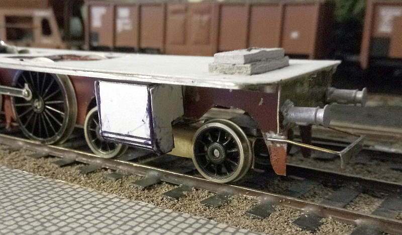
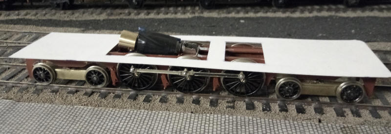
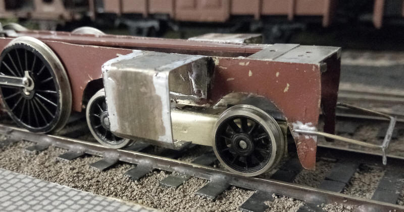
Before constructing the cylinders in metal I decided to construct a mock-up in cardboard to check clearances for the bogie.
The construction of the cylinders starts by bending a strip of brass (15mm wide) into the profile shown in the diagram, Bends are made by scoring the inside of the brass with a heavy duty craft knife before folding - this is much the same as bends in an etched kit. The brass is the soldered to the main frame and all edges are tinned with solder ready for the front and back faces of the cylinders to be fixed in place.
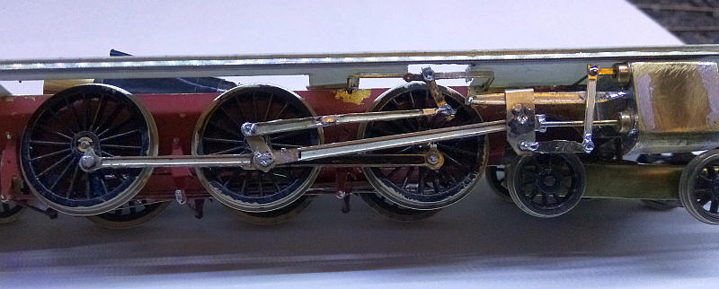
The valve gear in its raw and rather crude state is made from a mixture of modified Alan Gibson LMS S Scale etchings and various pieces of wire and small diameter top hat bearings. Once painted and weathered all will blend together.
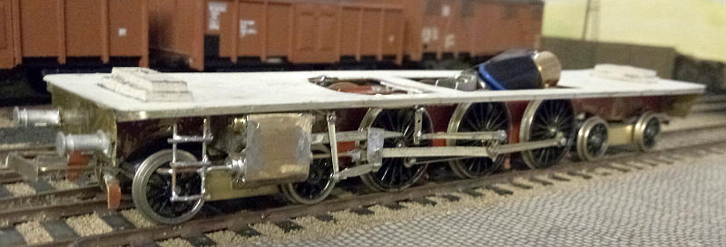
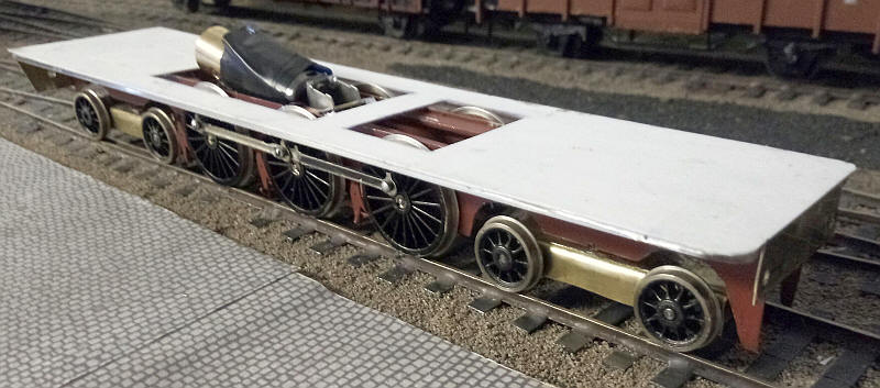
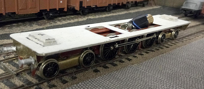
The chassis is now largely complete - the front surface of the cylinders have had various parts added to represent what is there on the real loco, such as the piston tail rods which despite the sharp curves on the layout can still be represented by a piece of brass wire soldered into a top hat bearing. The front steps have been mounted on the chassis - these were made from lengths of brass wire bent into a U shape and soldered into slots filed in the top of the chassis frames. Rungs are simply cross pieces of wire.
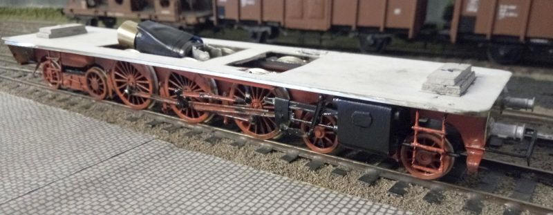
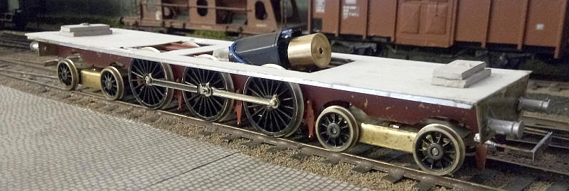
I've now added the brake gear to both bogies and painted the frames and wheels in a suitable slightly dirty red. On to the loco body!
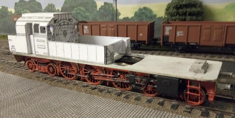
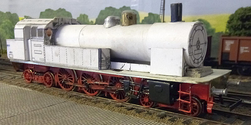
After the diagram shown at the top of this page had been rescaled to S Scale the side and end elevations were printed out on 220 gsm card. The sides were also printed out as mirror images to give both a left and right hand side. The cab and side tanks have been and after cutting out the windows and cab doors have been assembled. The fit of the parts was extremely accurate confirming again that this method of construction produces models with relatively little effort.
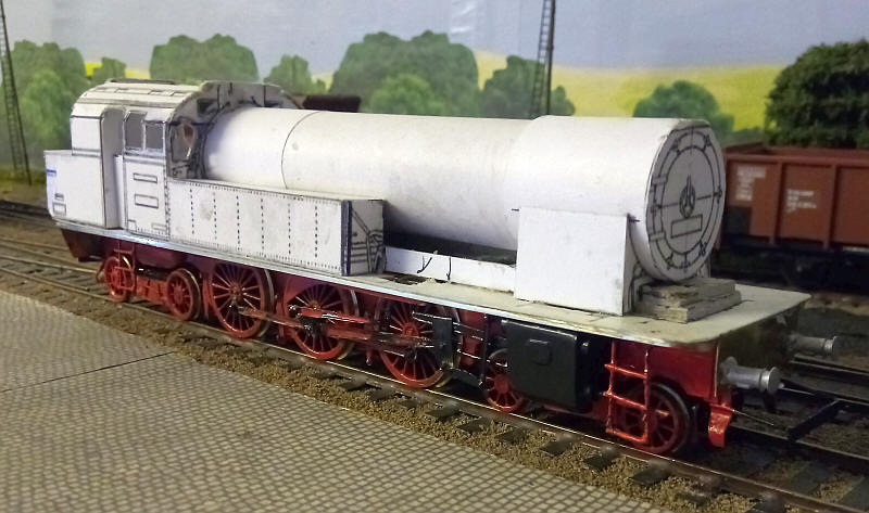
The boiler as far most of my models has a 20mm diameter plastic water pipe as a base with the required number of turns of thin card wrapped around it and secured with two part epoxy resin spread over the whole of the underside of the card. The BR78 has a much larger diameter smoke box than boiler barrel so this required further layers. I glued a Swiss coin, which has a tight fit in the plastic tube, to the front of the cab. This acts as a secure fixing point for one end of the boiler. The smoke box rests on a very large saddle which has been fabricated out of various layers of thin card and mounting board.
I've also replaced the wheels on the front bogie with slightly smaller ones (and also much deeper flanges) as the bogie kept derailing on the sharp curves. Clearances behind the cylinders are very tight so this is hardly surprising. The new arrangement has eliminated that problem.
A little progress with the chimney and two domes added. The chimney is from a length of plastic tube. To get the slight tapering I cut four slots at right angles to each other and slid in lengths of 10thou microstrip into the slots. A good dollop of Plastic Weld solution melts the plastic and gives a smooth finish. The tube is passed through a hole in the smoke box and glued in place to the bottom of the firebox and around the hole.
The rear dome is made from an Alan Gibson LMS which has had an additional layer of low melt solder added to the top and is then filed to the correct shape and glued in place. The front dome is made from a length of aluminum tube from a Pilot gold pen marker. The bottom is filed to the profile of the boiler top and then the whole of the interior of the tube is filled with epoxy resin. After this has dried more resin is added to the top and shaped and filed to give the correct rounded top. To secure I passed a length of wire up the centre of the dome and located this in a hole drilled on the centre line of the boiler. More epoxy resin secures the dome in place.
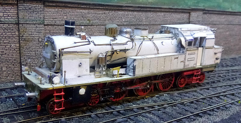
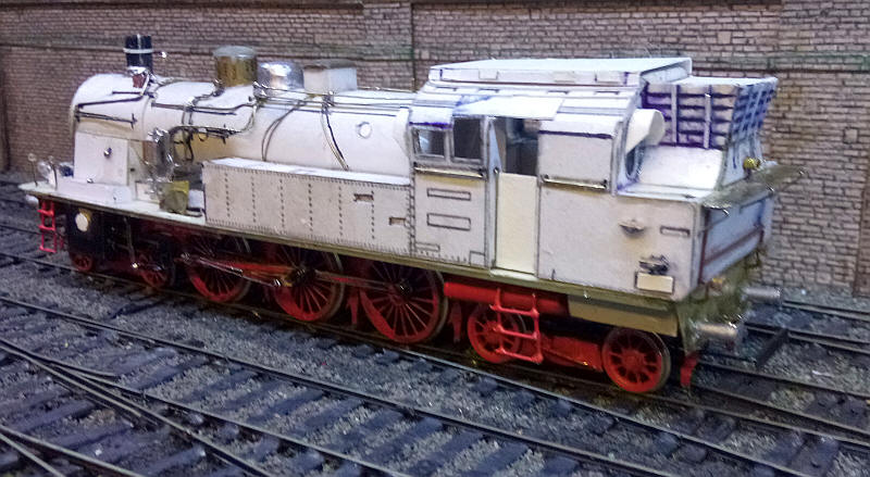
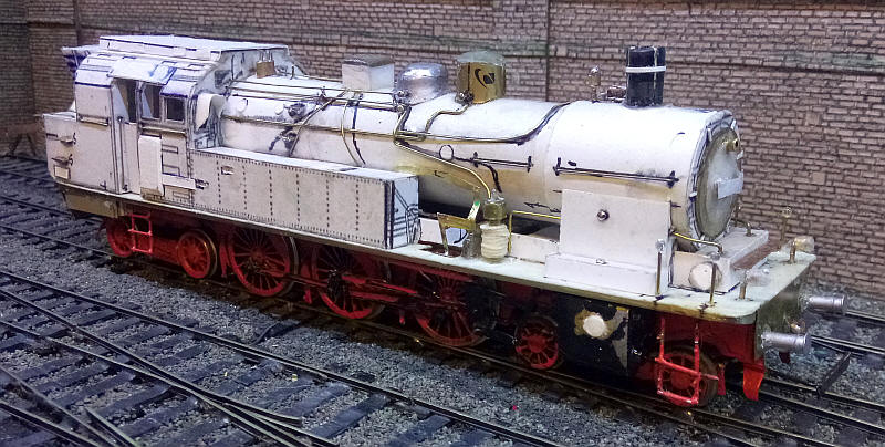
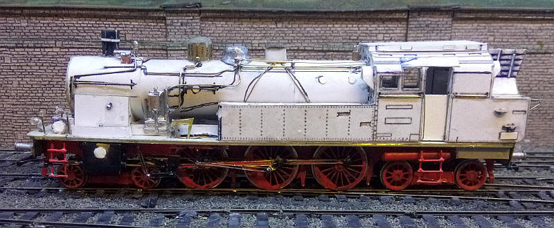
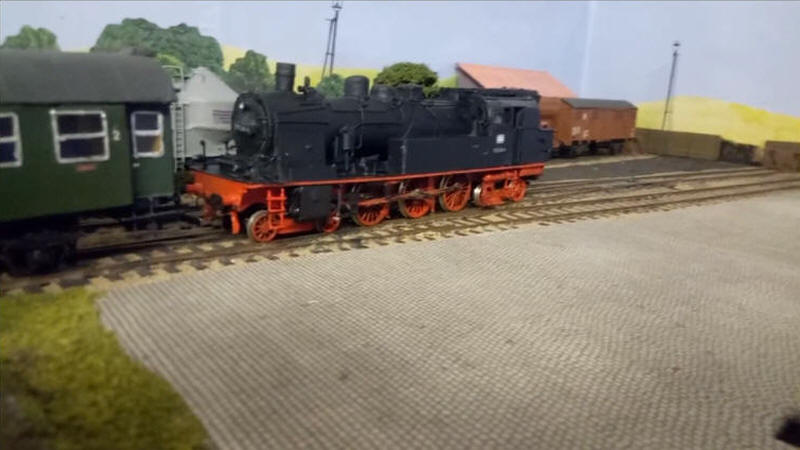
The three photos below show the models after the numerous details have been added. These have been made from brass wire, tube and strip as well as card either in strips or circles punched out of thin card.
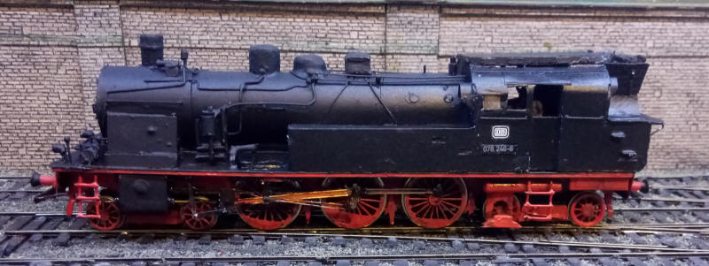
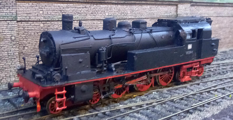
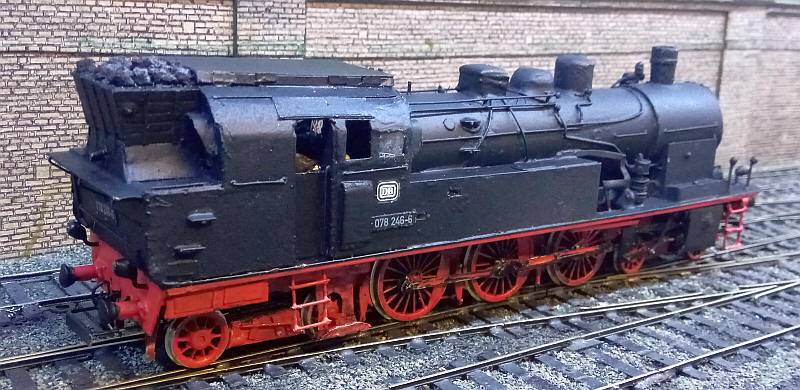
The three photos below show the painted model. A few additions have been made such as the equipment for the Indusi (German equivalent of the British AWS safety warning system). These can be seen on both sides of the loco in front of the leading axle of the rear bogie and also the raised area on the right hand side of the cap. Lettering is from Modellbahn Decals who produced teh transfers specially for this model in 1:64 scale.
Click on the photo below to see a short video of the model in action. The train runs off the Niederwangen layout and onto the British Pendle Midland to access the fiddle yard.
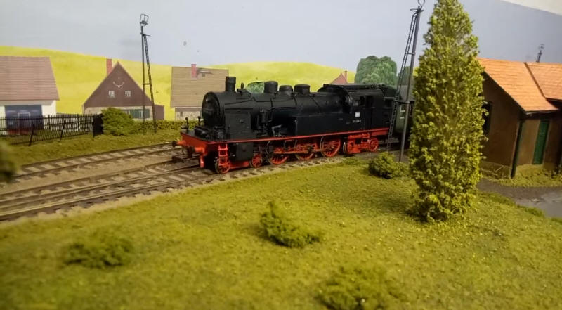
In the clip below we see the locomotive running around its train at Niederwangen.