Building a DB BR169 electric loco
Among the various pdfs that I have accumulated for building card models of German locomotives is one by Gunnar Dannehl. He has designed a detailed model which is for 1:38.
I found the results he obtained inspiring so have decided to try to build an operational model in S Scale using his ideas but making the individual parts based on re-scaled diagrams of the otiginal loco.
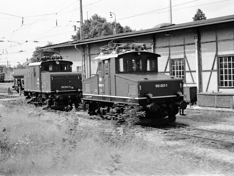
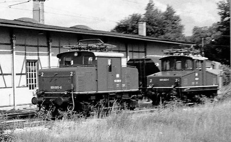
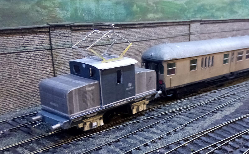
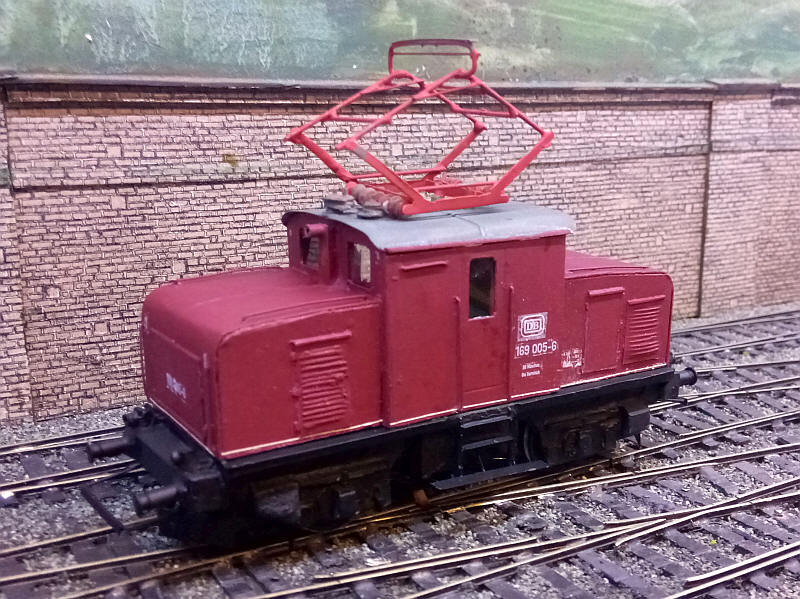
These two photos show 169.003 (one of the older 169s) and 169.005 at Murnau shed. The locos were used on freight and passenger trains on the branch to Oberamergau until the early 1980s.
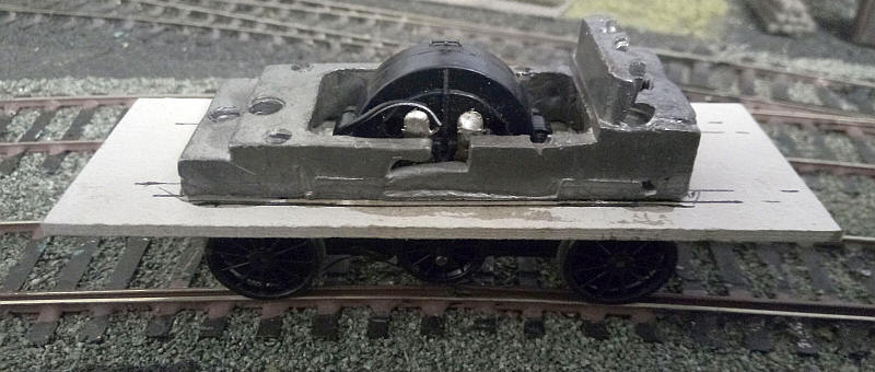
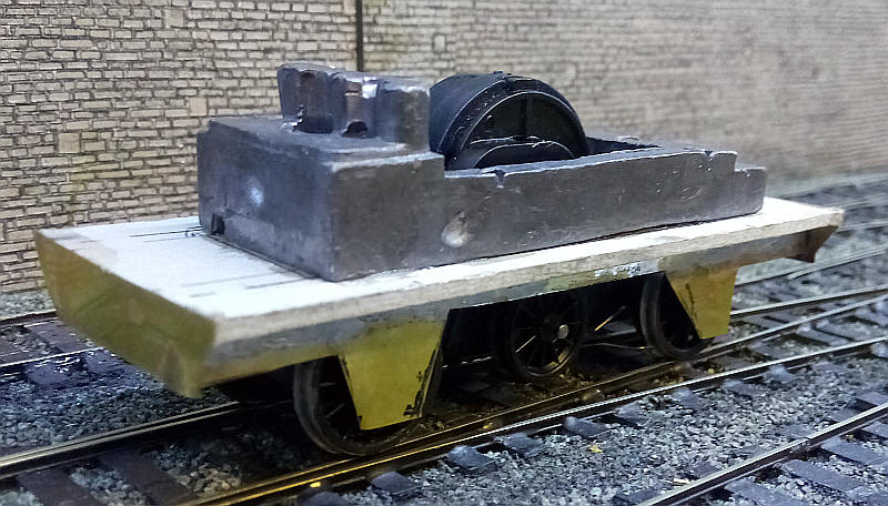
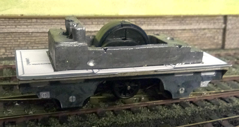
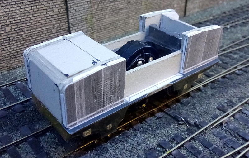
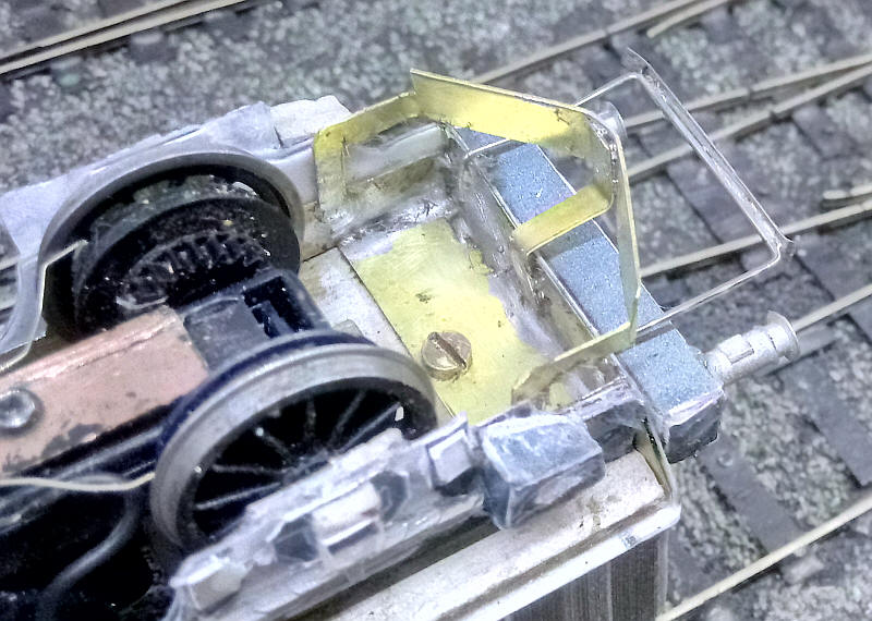
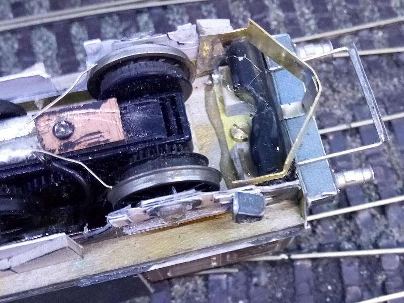
The construction starts by using an old tender drive unit from a Airfix Royal Scot. Amazingly the wheelbase is virtually correct for an S Scale model of 169.005. The original plastic wheels/ gears were removed from the OO Gauge axles. These were remounted on S Scale axles and Gibson tender wheels were added and gauged corectly.
A rectangular piece of greyboard was cut to size and a hole was cut out of the centre to clear the mechanism. The original weight was glued to the card and the assembly was then secured to the mounting points of the mechanism with self taping screws
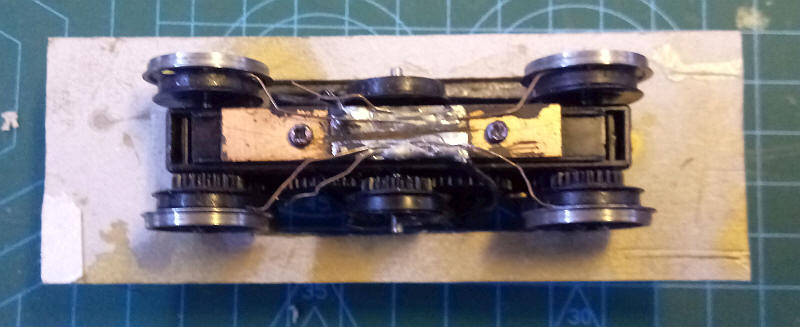
The underside of the mechanism showing the pick up wires.
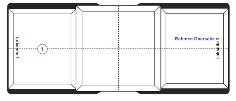
The next step constructing the model is to add the outer frames to the chassis. It was obvious that cardboard on its own wouldn't be sufficently strong and there would also be problems attching it to the underside of the footplate. I decided to use the outer frame part as a template for making an inner frame out of sheet brass.
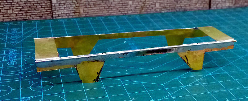
Using 0.01" (0.25mm) brass sheet I cut out a net of the two side frames and two stretchers. The brass was cut with a scalpel blade using repeated scoring until the unwanted sections of metal could be removed. The result shape was bent to produce what looks like a wagon chassi structure. The brass is obviously very flimsy but lengths of 1,00mm diameter brass wire were solderd along the top edges of the sides and the insides of the stretchers were flood with solder. The card outer frames can now be glued ot the metal.
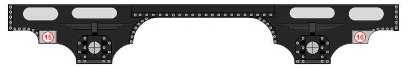
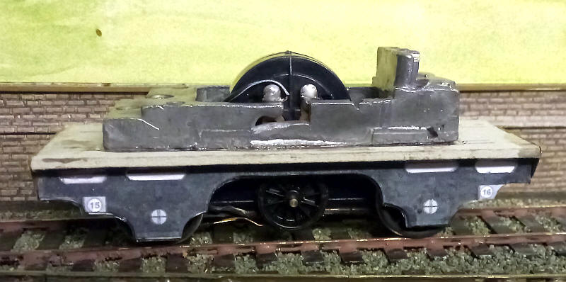
The backing plates for the buffer beams have been added. The mounting card was also cut back to the correct length.
The print out for the loco's outer frame was printed out three times and three layers of card were glued together with epoxy resin. The outer layer had the lightning cut out. The centre 4mm scale wheel is obvious in this view but will behind behind the cab steps.
The next part to be added was the top of the footplate. This had a hole cut in the centre to clear the motor.
Once glued to the mounting board the edges of both the mounting board and the thinner card for the footplate top were flooded with superglue to harden the edges.
The bonnet ends of the loco from the pdfs.
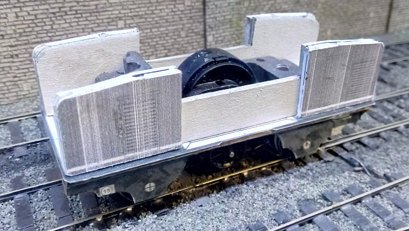
The loco's bonnet ends have been glued to some back pieces of mount board and placed loosely in place on the footplate. These form the sides of the loco with space for the cab in the middle,
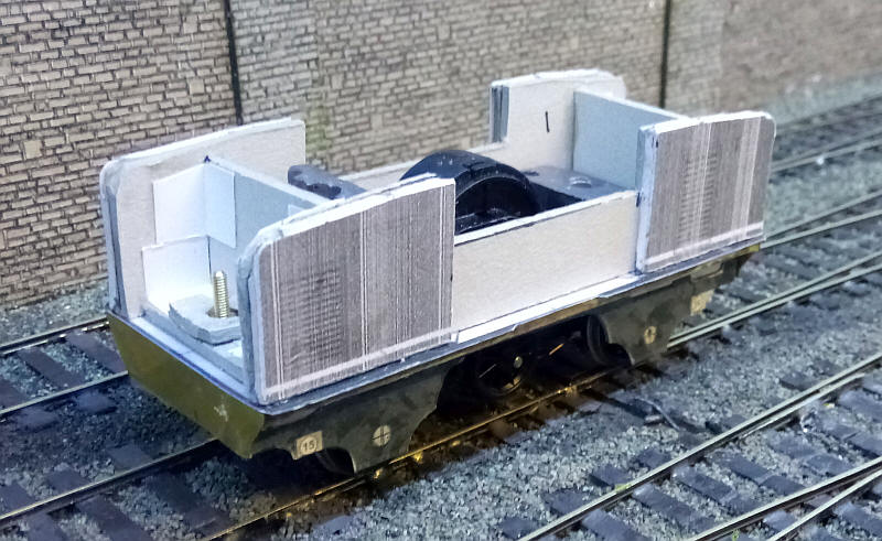
The bonnets have now been joined to each other using cross strips of mounting board. The entire unit is separate from the chassis and is held in place by bolts passing through captive nuts trapped inside card strips.
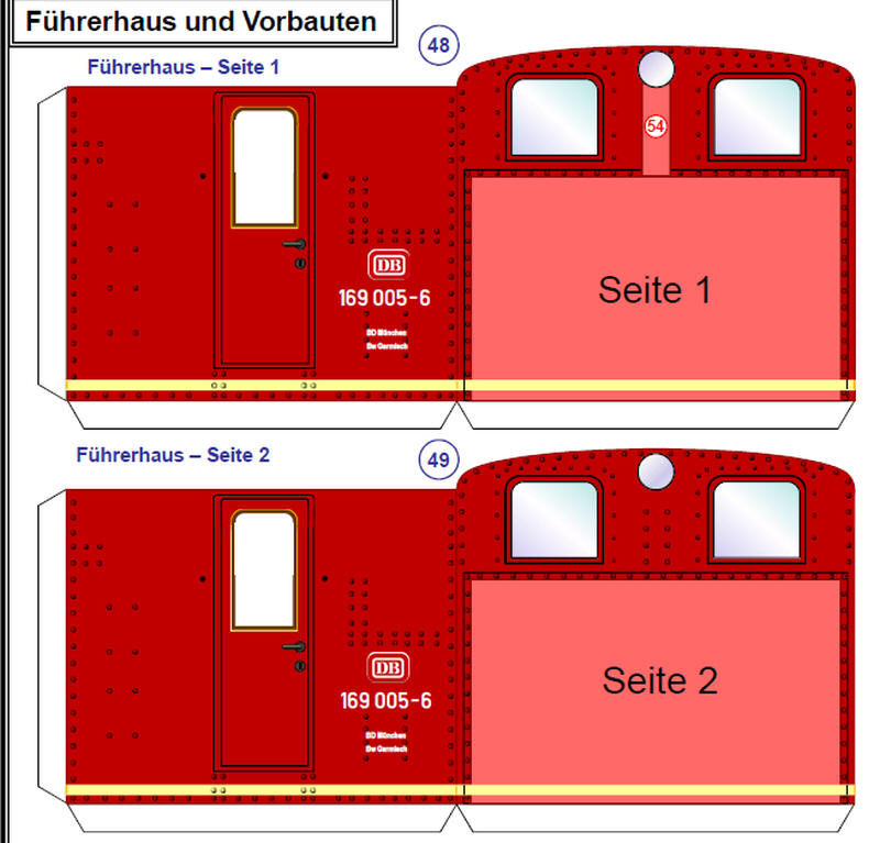
The outer layer of the cabs from the pdf.
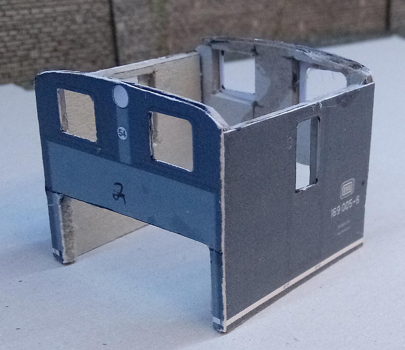
The two parts of the cab were cut out with a section of the cab front cut away at the bottom to clear the motor area. The cab sides were then assembled and strengthened with a inner layer of mounting board.
The cab is in place between the bonnets - a near perfect fit.
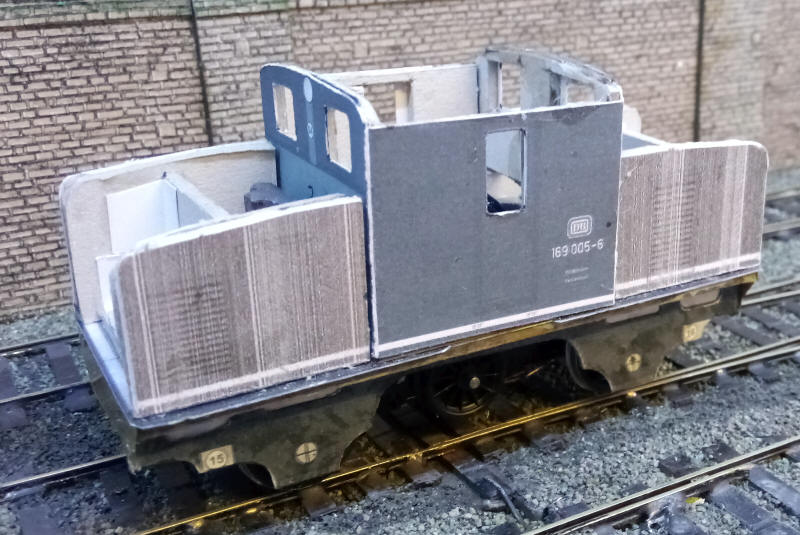
I've now added the top and front of the No.1 end bonnet using mounting board cut and shaped to give a firm base on which to glue the thin layer of card for the final surface.
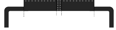
The tops of the bonnets have been added and the card template for the roof has been placed on the cab - the actual roof will be made from brass as it will need to be strong to support the pantograph.
The bufferbeam has been added using a fold up part as below:
To make the bufferbeam capable of supporting teh buffers the interior had three layers of mounting board glued inside.
The pdfs contain various parts to form the springs and axleboxes which have been added to the outer frame card sides. Once painted and weathered they should look convincing.
The buffers are cast metal British Railways wagon buffers similar to those fitted to the BR169s.
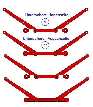
One of the major problems I expected to encounter was constructing the pantographs. The pdf kit has detailed instructions how to build a non working representation so I decided to use that method.
The image above shows the construction of the lower part of the pantographs with base and bottom arms as one unit. A print out of this was secured to a sheet of 0.16" brass sheet and lines scored through the paper leaving marks on the brass. This was then cut out using scissors and once straightened out was filed gently to give reasonably thin arms. On the prototype these are actually narrower than this but I've decided to follow the method used by firms such as Sommerfeldt and Roco.
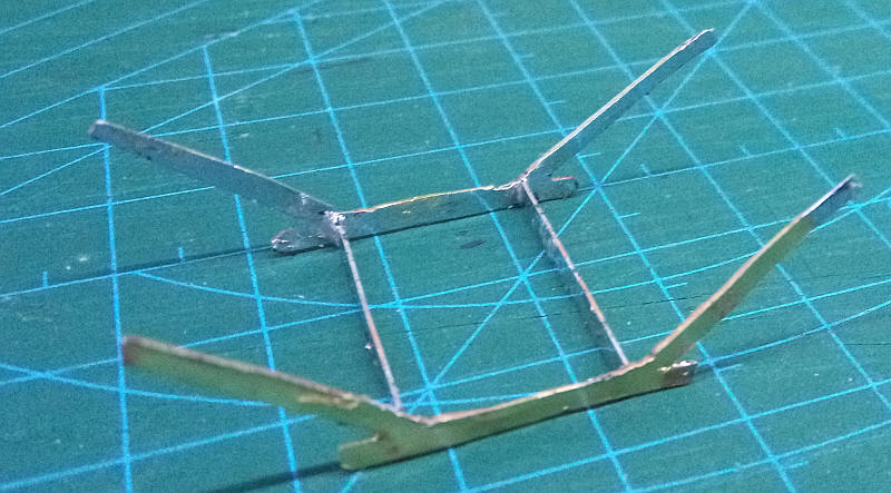
The lower part of the pantograph is assembled with cross bars soldered to the lower arms.
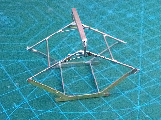
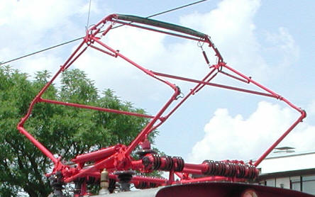
The rest of the pantograph has been added using nickel silver wire of 0.33, 0.7 and 0.9 diameter as well as phosphor bronze strip for the top of the collector. The photo on the right is of the real 169.005
I've placed the roof and pantograph in place to give an idea of what the finished loco will look like.
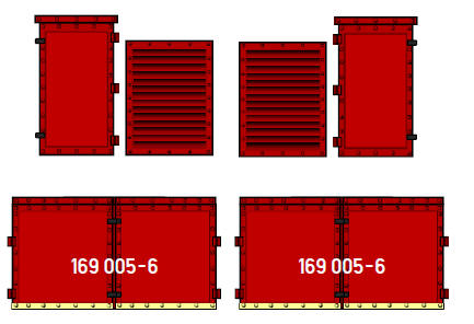
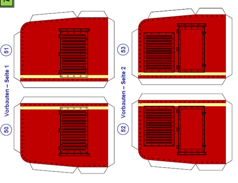
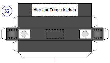
The BR 169 has some ventilation louvres on the sides of each bonnet. These are printed out on the pdfs as add on parts with the suggetsion that they can be made three-dimensional.
The method used is to cut through the card along the black lines. Then from the back slide the blade through the slots and lift the lower edge of each louvre. Then slide a piece of thin card through the slots in the same way and wiggle it from side to side. When all the slots have been treated this way a coat of superglue was spread over the back of the card.
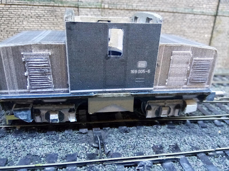
After this has dried the panels have the correct shape of the louvres fixed firmly in place and can be cut out and glued to the loco as in the photo.
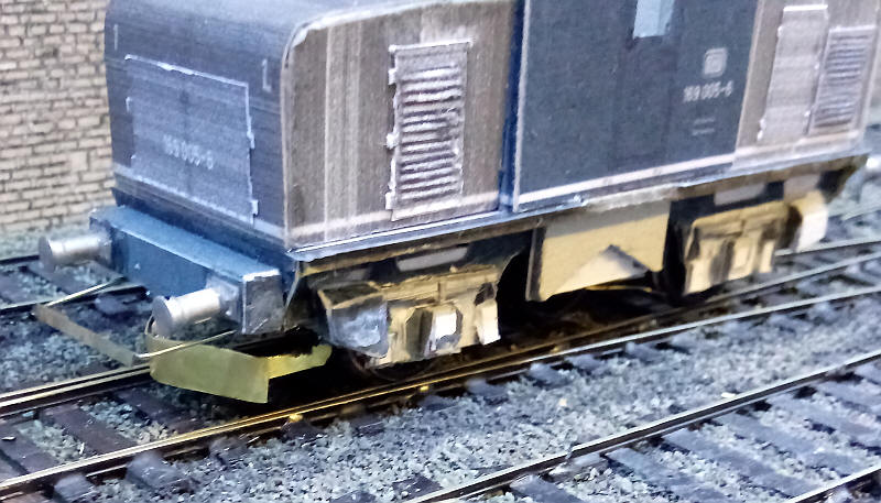
A distinctive feature of the locos is the permamently fitted snowploughs under the buffer beam. I used the printouts for these as a template for ones made out of brass as I felt that strength was necessary for these fragile parts.
 |
 |
As can be seen the plough is bent at the centre and is secured to the rear of the bufferbean with a piece of brass strip. The side legs of the plough are soldered to the inside of the underframe.
Behind the bufferbeams I've glued some plastic tube represent the air tanks. The tube is mounted on card spacers to lift it to the correct height and also has a slot filed in it to clear the bolt securing the body to the chassis.
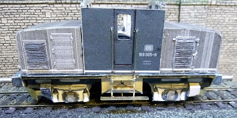
I've now added the cab handrails and steps. This has needed a small compromise as the handrails on the real locomotive extend down to just below the level of the footplate. I have secured the wires to holes in the cabside just above footplate level to allow the body to be removed easily.
The steps are made out of brass wire and nickel silver and brass strip. The wires are bent at the top and go into holes just below footplate level and are also bent to support the bottom step. The top step is glued to the underside of the footplate and also soldered to the wires. A middle step is soldered in position and then narrow nickel silver strips are solderd to the outer edges of the wire. Finally, a wire is bent and soldered to the underside of the bottom step and also into a hole in the card thus bracing the step firmly in place.
The pantograph frame has had its insulators added - these were made from discs of thin card stamped out using leather making hole punches. A hole was made through the centre of the discs and about 20 threaded on to a length of wire. This was soldered to the base of the pantograph frame, the card discs spaced out and the whole lot flooded with superglue. The three insulators on the roof were made in the same way. The roof is a sheet of .010 inch brass sheet to which the pantograph was soldered using nuts and wire as spacers.
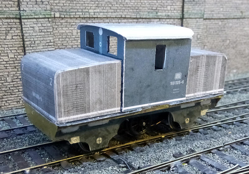
All the numerous handrails have been added as well as the curious system of pipes under one of the bonnets. There are still numerous small parts that need adding.
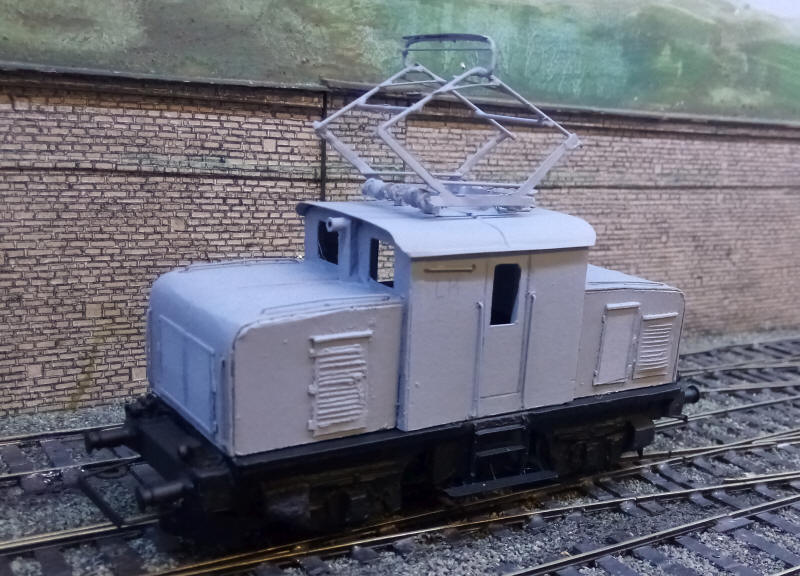
The model has now received its undercoat for the body and roof and a coat of black paint for everything under the footplate.
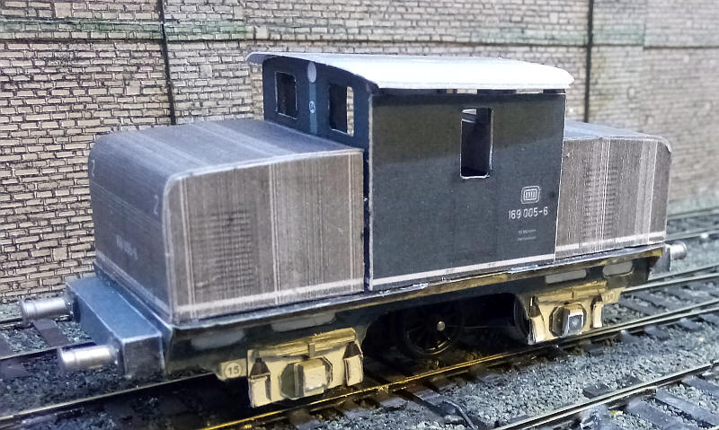
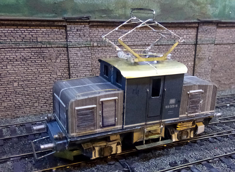
The completed model.