Building a DB BR64 and a BR86
I have felt for some time that I should have at least one German steam locomotive to run on Niederwangen. For a branch line there are two obvious choices: the BR64 2-6-2T or the larger BR86 2-8-2T. I saw several examples of both classes in Germany on my three visits between 1969 and 1971. The photo above is 086 346 at Hof shed in 1971
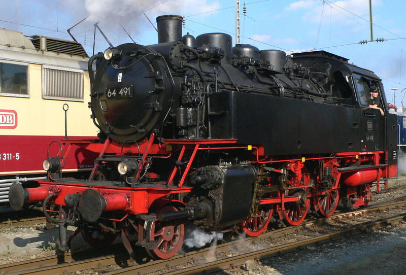
Although I saw a number of the smaller B64 locos I didn't take any photographs of them so here is a photo by
Plans of the locomotive are readily available on the internet as below.
Initially I decided to tackle the BR86 followed by the BR64.
BR86
For both locos there are available large scale 1:35 resin kit models which have detailed drawings of all the major components of the model, again available on the internet.
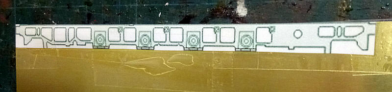
I'm going to use some of these drawings as a template for the chassis frames. The photo shows the drawing stuck to a piece of 0.16" brass sheet. The centre points for each axle hole were marked with a sharp compass point making sure that they are all in line by using a steel ruler.
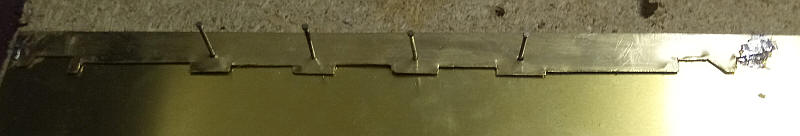
The first frame was cut out roughly using heavy duty scissors. The recesses at the bottom of the frame were cut by scoring heavily with a Stanley knife and then snapping off. The frame was then tack soldered to another sheet of brass and the holes drilled through and enlarged until large enough until moulding pins could be passed through. These were then hammered into a piece of chipboard. After the heads of the pins are removed they will act as a jig to set up the three coupling rods which will be assembled from Alan Gibson universal rods.
Whilst the original locomotive has large lightening holes cut into the frames I'm not going to attempt to cut these out as, by and large, they aren't really visible behind the wheels.
The basic chassis has now been assembled. The various stages were:
Fit the bearings in the axle holes after opening these out with broaches.
Lengths of double sided copper clad sleeper strip were soldered along the top edges of the frames sides.
Frame spacers were soldered in place with the frames being held in place with frame alignment jigs and also with axle rods passed through the bearings.
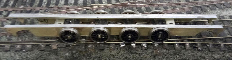
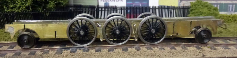
The bearing holes for the 2nd and 3rd axles were elongated at the top of the hole to give a small amount of vertical movement. The wheels fitted are not the correct size but have been used to prove that the chassis will traverse the sharp curves on the layout.
The result of this work was that the chassis did roll quite smoothly on the large radius points on the British layout but tended to derail on the German section which rather defeated the point of building the model.
My suspicion was that the RP25 wheel profile (with their small flanges) of the Markits wheels was the cause of the problem.
BR64
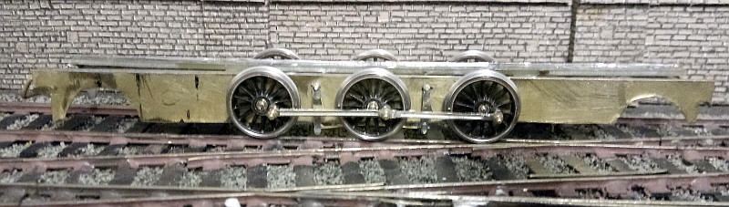
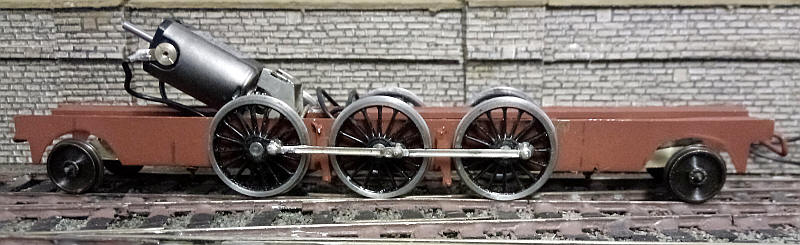
I decided therefore to try again with the BR64 2-6-2T for which I had suitable Alan Gibson wheels with EM Gauge profile wheels and a deeper flange.
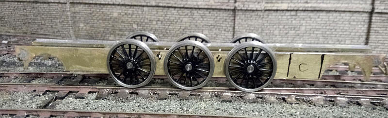
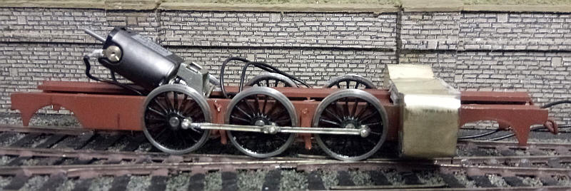
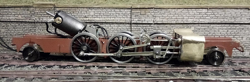
This is the result with a chassis that rolls without derailing. Using Gibson wheels does, of course mean that I'll need to be a lot more careful setting up the quartering of the wheels.
The brake hangers have been added suspended on wires passed through holes near the top of the frames. I've not added the brakes for the front driving wheels (the right side of the photo) as they will be hidden behind the valve gear. The pony trucks have temporary disc wheels, although the many of the real BR64s had these anyway.
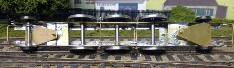
Cross wires have been added at the bottom of the brake hangers and two longitudinal "pull rods" have been soldered to them to give some rigidity.
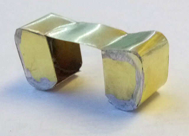
The pony trucks are very simple fabrications made from a plate of 0.16" brass sheet with two bearings soldered on the outside edges.....
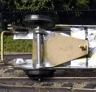
....as seen here
I've now assembled the four coupling rods from a set of Alan Gibson "Universal" rods. These have to be cut to the lengths required and the front and back section of each rod soldered together. I use some alignment jigs to set them up. The Gibson wheels have been removed from the chassis and some (undersized) Markits wheels used to check that the rods will rotate smoothly.
No doubt I shall have problems when I have to quarter the Gibson wheels but at least I know the rods are correct!
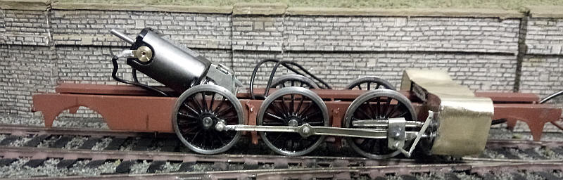
A few hours' work has seen more progress. The frames have been sprayed in brown undercoat. I feel that this will be closer to the dirty red/brown colour that German steam locos ran with rather than spraying it black. Touching up around the wheels and cylinders with suitable give the correct appearance in due course.
The Gibson wheels have been fitted with the more substantial Markits crankpins. To do this the crankpin holes were opened up with a fine broach and the holes were then tapped so that the Markits crankpins can be screwed in tightly. A smearing of two part epoxy resin around the thread should lock them in place and also protects the plastic wheel centres when the crankpin washers are soldered in place - the epoxy appears to melt slightly and then solidifies before the plastic is affected. The plastic centres of the wheels are also pressed out of the metal tyres and superglue applied to four spots inside the tyres before pressing the plastic centres back in place.
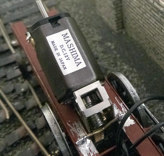
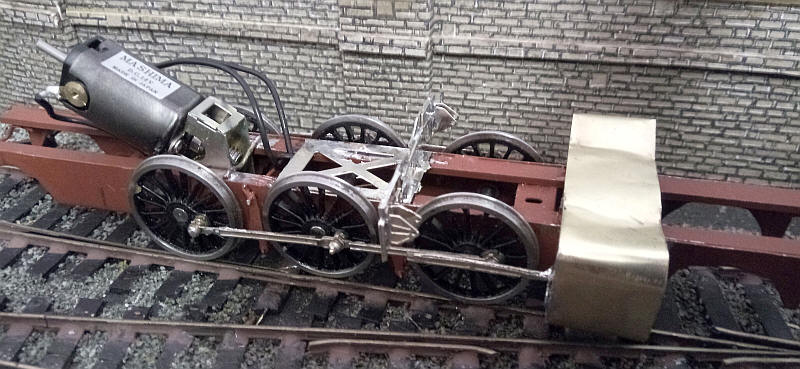
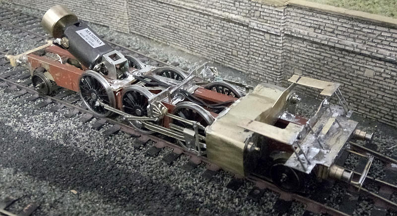
The Mashima motor and Markits gearbox had already been assembled and slots perfectly in place between copperclad sleeper strip that I've used for the frame strengtheners.
The wheels were quartered - the rear pair first and once the rods on these two axles revolved smoothly the leading axle and rods were added. Test running with the rods held in place revealed no problems so I've soldered in place the crankpins on all three axles. When I add the return crank to the centre axle I'll flood the joint with oil to prevent everything soldering up solid.
So far test running suggests that the chassis rolls smoothly with no binding.
Fitting the cylinders and the Heusinger valve gear is probably going to be the most difficult part of construction. In the photo above I've made a card mock up of the cylinder block using print outs for the scans of the parts from the resin kit. The cylinders will need to be slightly wider than scale to give sufficient clearance for the moving parts.
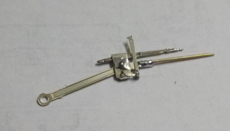
I'm assembling the valve gear out of a variety of Gibson etchings. The connecting rod and single slidebar are from a Stanier 2-6-4T. The connecting rod has had the large hole opened up so that it will fit snugly over the fixing washer on the centre crankpin. The rod has also been shortened to the correct distance for the BR64 and a new hole drilled at the crosshead end. The remaining length of the connecting rod is turned through 90 degrees and has a length of brass wire soldered to the fluting in the rod.
The crosshead is folded up from a strip of thin nickel silver to give a square shaped section at the top into which the slidebar will be fitted. Two holes are drilled lower down for the pivot for the connecting rod and piston rod.
The union link and combination link are from a Crab kit. The crosshead is folded up from a strip of thin nickel silver to give an open square section at one end. This fits over the slidebar as seen in the photo.
Using the print outs from the resin kit as a template I cut out the 4 pieces needed for the cylinder ends from 0.10" brass. A strip of 0.05" brass was cut for the cylinder block wrapper. This is where the card mock up proved its worth as I was able to measure the precise length needed. The wrapper was carefully soldered to the cylinder ends as in the photo above. Overall the cylinder block is about 3mm wider than scale but is still within the overall width of the loco body. With wheels that are not scale width it is impossible to get sufficient clearance behind the valve hear and coupling rods without this compromise.
The cylinder block has been placed over the frames with temporary packing from card to hold it at the correct height.
The cylinders are now fixed in position and soldered to the frames at the front. The slidebar needed shortening slightly but the connecting rod moves smoothly when under power.
I've now added the brackets that support the expansion link. These come from a Gibson Stanier 2-6-4T etch. The bracket support originally came with a base plate which folds at right angles and forms a frame spacer. My modification was to snap this off, cut the bracket support in half and re-solder the frame spacer to the bracket support with a gap of about 4mm in the centre, The frame spacer sits snugly on top of the longitudinal pieces of double sided sleeper strip and between the frames.
The actual brackets are soldered into slots in the support ensuring that the holes in them line up so that the expansion links can pivot.
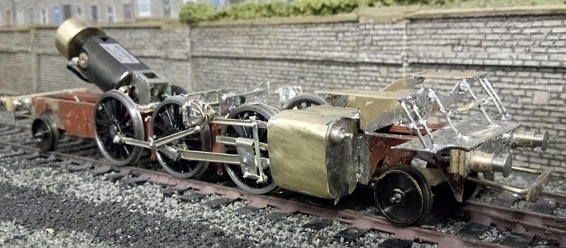
The valve gear is now complete on one side of the locomotive. The extra parts come from a Gibson 'Crab' chassis etch which, by chance, have the right dimensions.
The valve stem guide at the top of the cylinder is a brass top hat axle bearing into which is soldered the radius bar. The expansion link was shortened and held in place on the supports by a piece of wire onto which a length of brass tube was placed to stop the link moving from side to side. The return crank and eccentric rod together with the expansion link were put in place as a separate unit with the middle wheels crankpin being covered with oil and a sliver of paper to stop everything being soldered solid. Test running on the bench and the track revea that so far I have a very smooth running chassis.
The cylinder looks a little lopsided in the photo due to the way the light is reflecting on the metal but is actually correct.
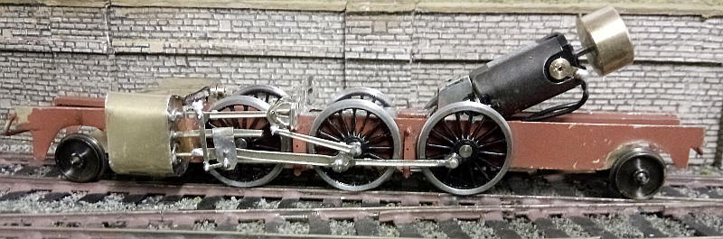
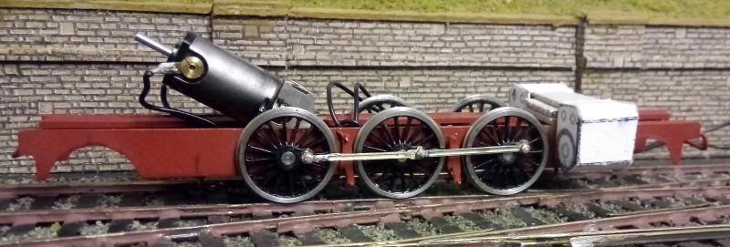
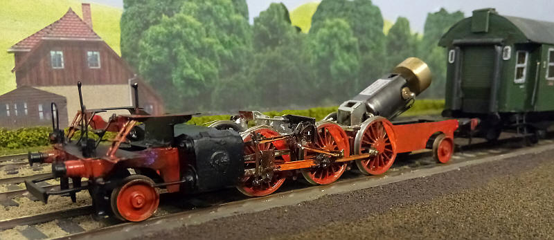
The other side of the valve gear has been completed and pickup wires added so the chassis now runs on the track. With plenty of weight temporarily added running is pleasingly good and will no doubt get better as the chassis is run in. I've added a fly wheel which gives a little more momentum. The motor and flywheel will be largely hidden within the large cab and coal bunker.
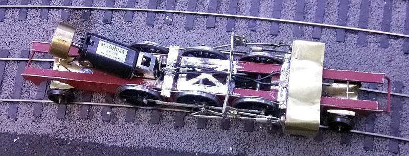
There are certain aspects of the chassis that needed some improvement. First I decided to add pickups to the top of the wheels (in addition to those already fitted bearing on the backs of the wheels). These and the various wires can be seen on top of the chassis. They will be completely hidden by the side tanks which will
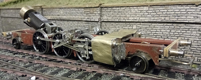
The two pony trucks have been fitted with a restraining device which restricts both vertical and sideways movement once removed from the track. This is simply a brass rod soldered to the underside of the copper clad strips running along the frame sides. Another length of wire is soldered to the top of the pony truck frame and bent so that it hooks over the brass rod. This arrangement can be seen above the two pony trucks in the photo.
There are various things to be seen here. The first is that I've done some heavy filing on both the top and bottom of the cylinders as they were actually slightly too deep due to the extra thickness caused by the cylinder wrappers.
The buffer beams and coupling bars have been added. The buffer beams are two pieces of copperclad sleeper strip. The back face is soldered to the end of the frames and then a second layer superglued to the first layer. Holes were drilled for the brass buffer headstocks which together with the buffer heads were soldered to both the front and rear copper surfaces of the buffer beams.
The coupling bar is a U shaped length of 1mm brass wires soldered to the inside of the frames with a strip of brass sheet soldered onto the wire to act as a buffing plate for the wagon or carriage couplings. I'm using the plug in NEM Hornby tension lock couplings on the rolling stock as they have a metal hook which can be lifted with a magnet on a stick.
These two photos show the arrangement of the footplates and steps at the front of the loco. These need to be part of the chassis for the sake of rigidity. They are made out of a combination of brass sheet and nickel silver wires.
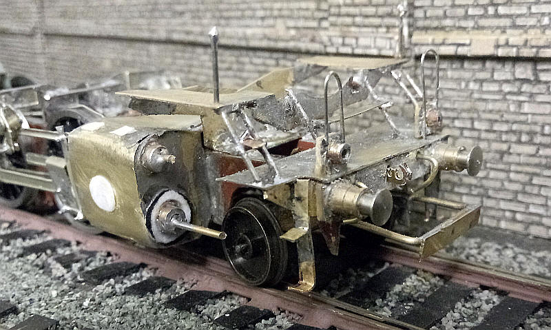
The final parts have been added to the front of the loco.
The chassis is now completed and painted.
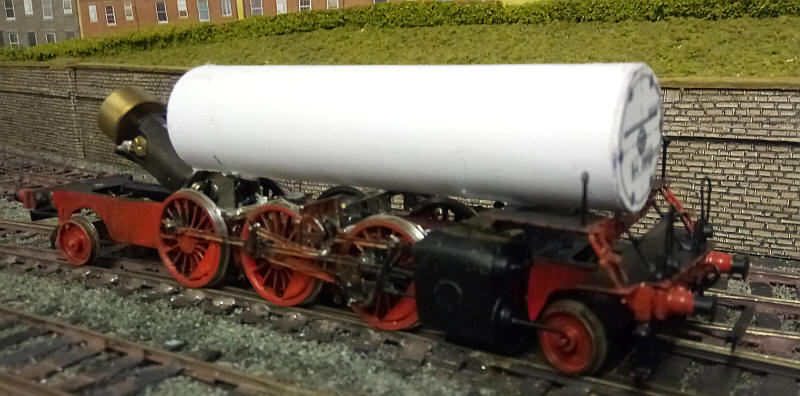
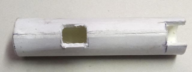
Moving on to the loco's superstructure the first part is the boiler. It is made from a length of 20mm diameter plastic piping around which are rolled and glued sufficient layers of card to bulk it out to 25mm diameter. A disc of card has been cut from a photocopy of the front of the boiler. This has been strengthened inside by gluing on several discs of card pushed down the centre of the tube.
At the rear of the boiler a small slot has been cut in the base of the boiler to give clearance around the gearbox.
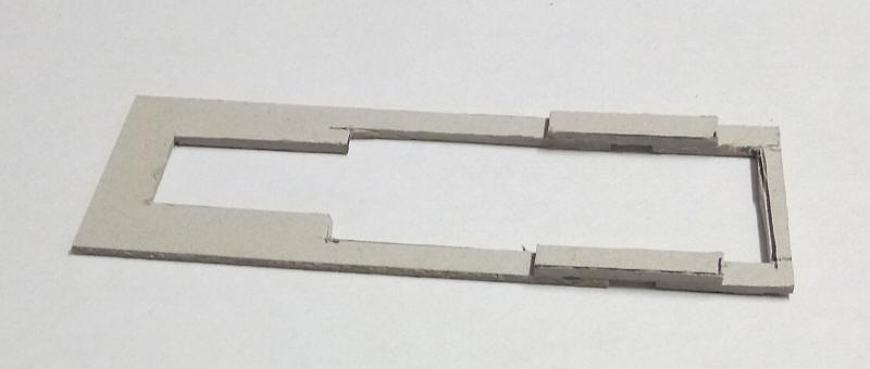
The whole of the superstructure is going to be based on this internal frame made up of 1.5mm greyboard. The raised areas join the front and rear sections of the U shaped ends. They will sit over the top part of motion bracket supports which will be hidden behind the water tank sides.
The frame has been placed loosely in position.
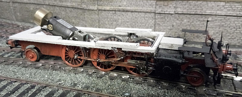
Two longitudinal pieces of card have been added. These will be concealed within the cab sides and water tanks.
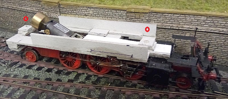
The superstructure frame is secured to the chassis by two nuts/ bolts. The nuts are locked in place by trapping the nuts in a slot in pieces of card which are then covered with another piece of card (the red circles show where they are.
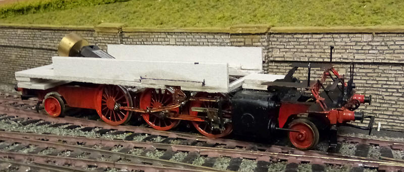
To strengthen the superstructure frame I have added further pieces of card in the centre which have packing pieces underneath that bear directly on the the chassis frames. This support down the middle of the superstructure frame is set at the correct height for the bottom of the boiler to sit on.
The boiler has had a slot cut in the underside to allow the front securing point to sit inside the boiler. After removing the outer layers of card a small drill bit was used to cut slots in the plastic inner boiler tube.
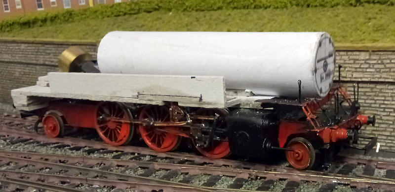
The boiler is positioned in the correct place but not fastened down.
I used this diagram found onthe internet and rescaled it to S Scale and printed out multiple copies on thin card.
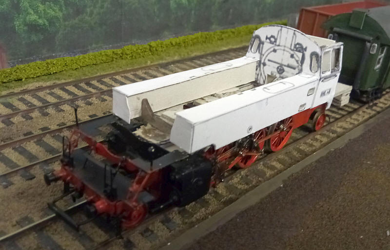
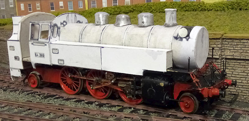
This photo shows the first stages in the construction of the loco body with the combined cab sides and side tanks printed out together with the front of the cab as well as the tops of the side tanks. The thin card has been strengthened with a layer of thick greyboard. The water tanks are made up of four layers of board glued to each other and then covered with layers of white card along the tops and front. I've also soldered short lengths of brass rod to the underside of the footplate above the cylinders. These will support the front of the water tanks and ensure that the underside lines up correctly with the footplate.
The boiler is placed loosely between the tanks. I've lengthened the smokebox area of the boiler by gluing on a disc of mounting board. This gives teh distinctive seam that is visible on photos of the BR64s .
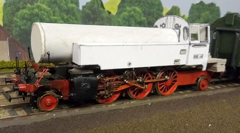
I've now added the rear cab wall and the coal bunker. This was a separate assembly made up of four main pieces of card cut straight from the plan; the rear cab wall, the two bunker sides with the upward sweeping curved section and teh rear of the bunker. The entire assembly is strengthened with additional layers of greyboard. The top of the coal bunker have been filed to give a narrow edge on the rear.
Just visible on the inside of the cab is a stengthening piece of card that I feel is necessary although I don't think the real lcoos had these.
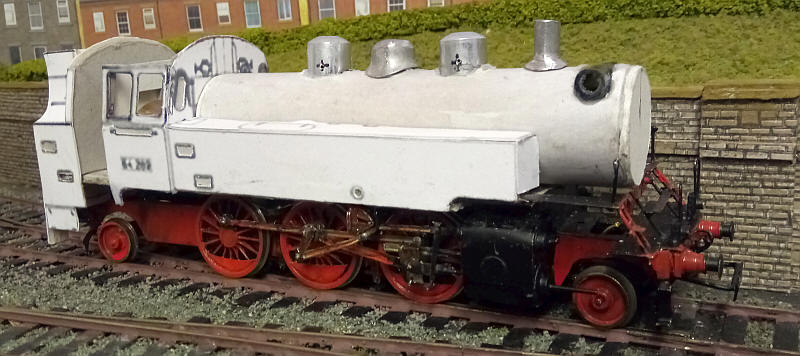
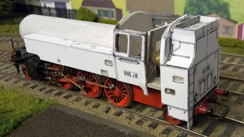
The main boiler parts have been secured in place on the boiler.
A job that I had not been looking forward to was adding the three "domes" , the loco chimney and the pre-heating device above the smokebox.
For the outer domes I found some correctly sized and shaped aluminium tubes that originally came from Pilot gold and silver marker pens. These were filled in front inside the boiler with epoxy resin to make them stronger and to give a base which could be glued to the boiler. When set a hole was drilled up the centre of the epoxy and a length of brass wire was stuck in place. Holes were then drilled along the centre of the boiler for the domes to be located. I also filed the top of the boiler flat where the domes sit. The central dome is a Gibson one filed to give the correct profile for the BR64.
The chimney is a white metal casting made by for the S Scale Society for a LNER Y7 0-4-0T. This tapers in to the base. I've cut the casting to the correct length and done some filing ot the base.
The slot in the front of the smokebox has a length of plastic tube glued in place to form the pre-heater device.
I've also added some lead weights inside the boiler and along the inner side of the water tanks.
PUTTING THINGS RIGHT!
I've become unhappy about certain aspects of the model - these were dimensional and proprtional discrepancies caused by working initially from a diagram that wasn't accurate.
To correct these errors I shortened the top footplate by a couple of millimetres and extended the side tanks by the same amount. This meant replacing the front half of the side tanks. Fortunately there is a line of rivets about half way down the tank so that's where I decided to make the cut.
To finish the main boiler structure 10 thou microstrip was glued in place to represent the quite prominent boiler bands. The narrow cast chimney has a had a layer of paper superglued around it and a strip of microstrip has been used to form the lip at the top.
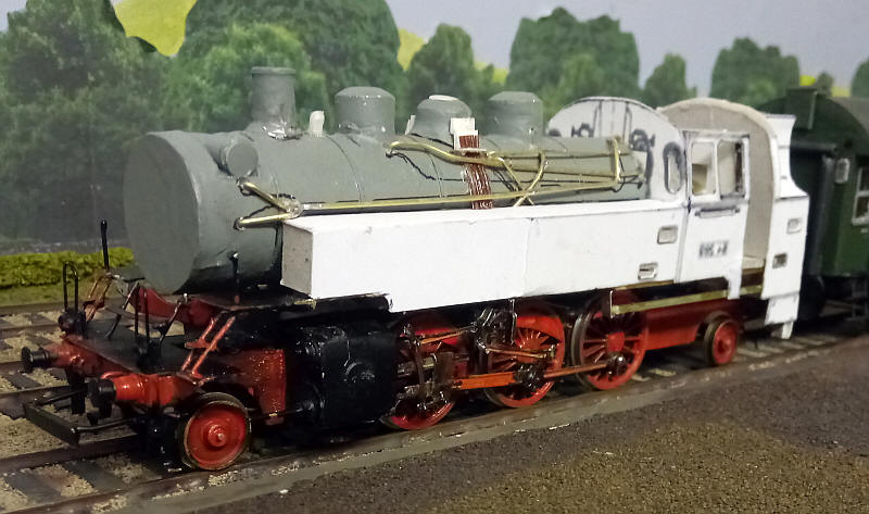
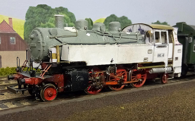
In order to make adding the pipework easier I gave the boiler a spray of grey primer. This shows up some of the problems such as the rough surface of the chimney which will be replaced.
The boiler has a multitude of pipes of different sizes and shapes and from photographic evidence no two locomotives seem to have exactly the same arrangement! I've used various thicknesses of brass wire and brown plastic micro-rod.
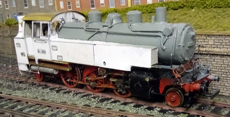
I've replaced the chimney with a brass tube and also moved it a couple of millimetres forward. The chimney has a very slight taper inwards towards the bottom. This was achieved by sawing a slot lengthwise down the tube leaving just a millimetre uncut at the bottom. Then a piece of brass was forced into the slot at the top and the cut filled with solder.
After several attempts to replicate the smokebox door I feel I have managed a reasonable representation of it. A base was made from a disc of thin card with four circles of descending size glued on to it. Then a disc of paper was glued down on to the base shaping and slightly distorting the paper so that it formed a dome shape in the centre but with a flat ring around the outside. This was then soaked in superglue to harden it. Then it was stuck to a thicker disc of mounting card and the edges filed to a rounded profile. This was glued ot the front of the smokebox and various pieces of plastic strip glued in place t0 represent the door hinges and securing cleats. A handle, number plate and headlight were added .
I've also now permamently secured the boiler to rest of the body as some of the next steps require parts to be connected between the boiler and the rest of the body.
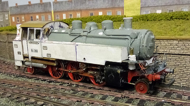
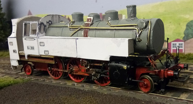
I've now added a few more details such as the rim on the chimney and the various pumps and air compressors at the front of the locomotive.
On the boiler the washout plugs are ovals of card whilst on the domes there are representations of the various handles which are small washers soldered to wires.
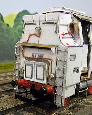
There's a lot of detail to add to the back of the bunker: ladders soldered up from nickel silver wire, handrails and headlamps from brass tube and wire conduits from plastic microrod.
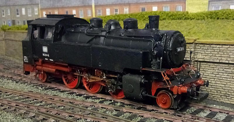
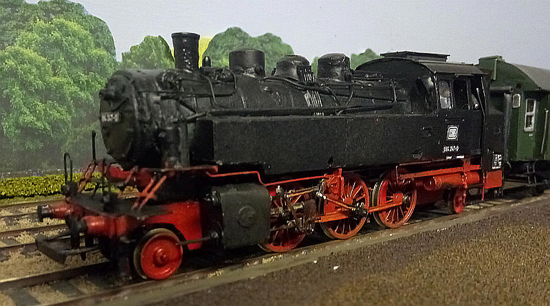
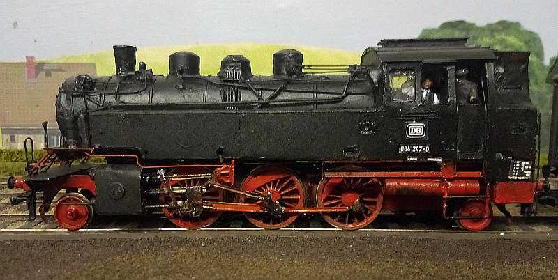
The loco is now completed. The photos show it after painting, adding glazing and a crew. The lettering is a combination of transfers and images resized from photographs of the real loco.
If you click on the photo above a short video of the loco in action will play.
064 247 is a locomotive that I saw in 1971 in Weiden.