Building a DB BR 86 2-8-2T
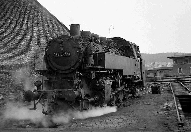
Having built a BR64 2-6-2T I have decided to construct a model of the larger BR86 2-8-2T of which I saw several examples in Germany on my three visits between 1969 and 1971. The photo above is 086 346 at Hof shed in 1971.
For both locos there are available large scale 1:35 resin kit models which have detailed drawings of all the major components of the model, again available on the internet.
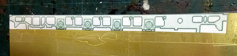
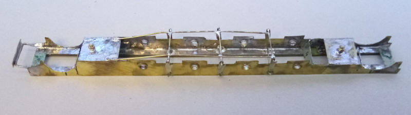
I'm going to use some of these drawings as a template for the chassis frames. The photo shows the drawing stuck to a piece of 0.16" brass sheet. The centre points for each axle hole were marked with a sharp compass point making sure that they are all in line by using a steel ruler.
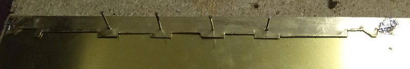
The first frame was cut out roughly using heavy duty scissors. The recesses at the bottom of the frame were cut by scoring heavily with a Stanley knife and then snapping off. The frame was then tack soldered to another sheet of brass and the holes drilled through and enlarged until large enough until moulding pins could be passed through. These were then hammered into a piece of chipboard. After the heads of the pins are removed they will act as a jig to set up the three coupling rods which will be assembled from Alan Gibson universal rods.
Whilst the original locomotive has large lightening holes cut into the frames I'm not going to attempt to cut these out as, by and large, they aren't really visible behind the wheels.
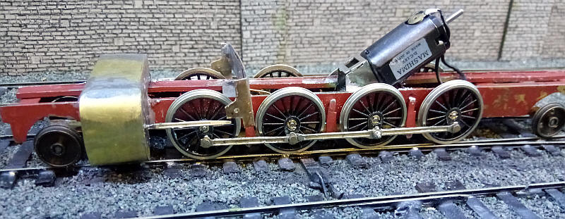
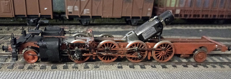
The basic chassis has now been assembled. The various stages were:
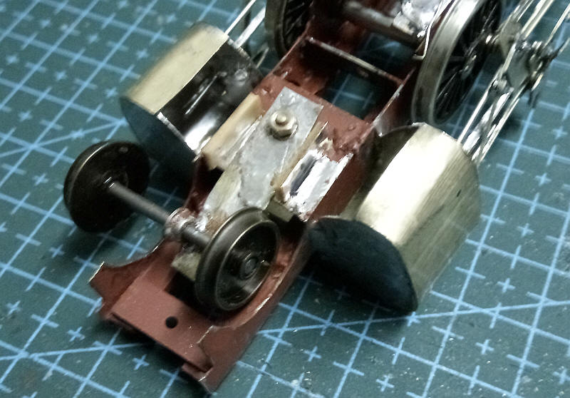
Fit the bearings in the axle holes after opening these out with broaches.
Lengths of double sided copper clad sleeper strip were soldered along the top edges of the frames sides.
Frame spacers were soldered in place with the frames being held in place with frame alignment jigs and also with axle rods passed through the bearings.
The bearing holes for the 2nd and 3rd axles were elongated at the top of the hole to give a small amount of vertical movement.
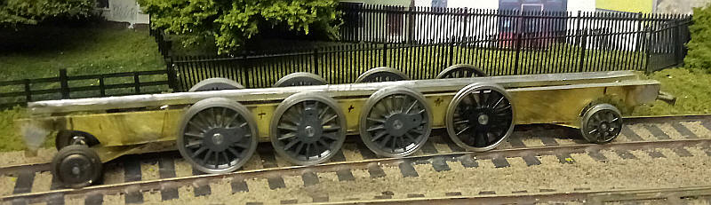
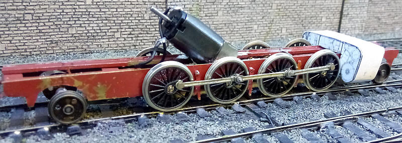
The chassis has been fitted with some spare Alan Gibson wheels of the same diameter but with different crank throws. These will be replaced with Markits wheels.
Brake gear has been added.
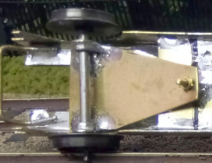
The pony trucks are simple triangles of brass with top hat bearings soldered in place on the edges. They pivot on bolts soldered to the spacers.
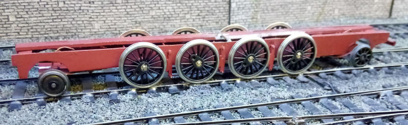
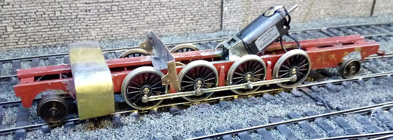
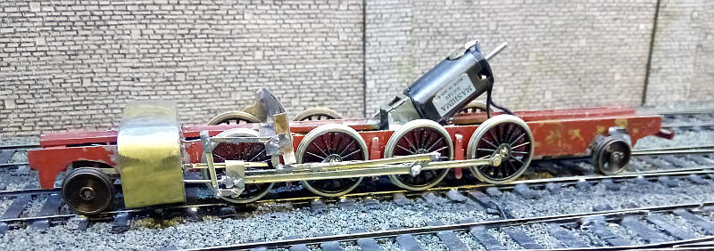
The chassis has now been sprayed with reddish brown primer and the Markits wheels mounted. The basic chassis traverses the layout satisfactorily.
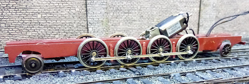
The coupling rods have now being added and the chassis runs under power.
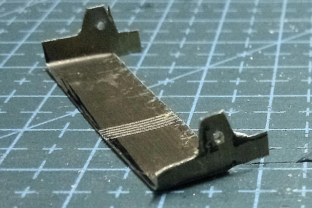
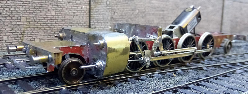
Before making the cylinder assembly in brass I've made a card mockup.
I've decided to build the cylinders in a similar way to the method used in some of the Alan Gibson British kits. I've drawn out on a sheet of brass the outlines of the front and rear faces of the cylinder with a 15mm wide strip of brass separating the opposite faces. The brass is then cut out using sharp scissors and the straight edges scored with a heavy craft knife. The unwanted sections between the inner edges of the cylinders are bent and snapped out. The cylinder faces and the spacing section are then bent at right angles to produce the assembly seen above.
The cylinder assembly is seen loosely in place - careful checking against the diagram shows that the assembly is at the correct height.
The cylinders have now had the outer wrapper added and are shown temporarily in place.
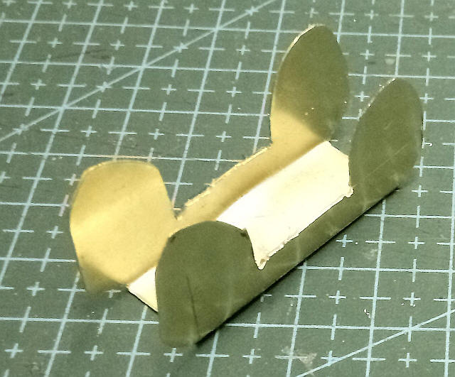
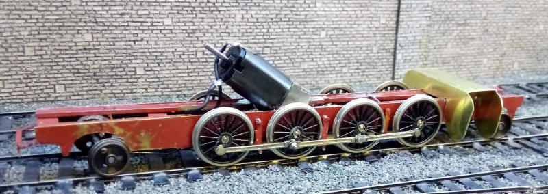
I've now made a very basic support for the expansion link. When I built the BR64 2-6-2T I was able to use a slightly modified part from an Alan Gibson Stanier 2-6-4T kit which was visually similar but for the BR86 the support was completely different. I've cut one from a sheet of sheet brass. The centre part will be soldered to the top of the frames - note the scored lines are unimportant and just happened to be on the piece of brass that I used. The holes for the pivot wire have been drilled through the brass.
I experienced some problems with the pony trucks running around my sharp curves. Whilst the original method had worked well on the shorter wheelbase of the BR64 2-6-2T the BR86 2-8-2T was considerably longer and derailments occurred. The solution was relatively simple and can be seen above. The pony truck frame is now a narrow strip of brass with two top hat bearings soldered to it. The bearings have been opened up with a broach allowing the axles to slide from side to side easily - there is also a little more lateral and vertical side play. In addition I have soldered some strips of copperclad paxolin sleeper strips to the spacer on which the pony truck pivots. This limits the sideways movement of the pony truck frame slightly and ensures that the wheels stay in line with the rails on curves.
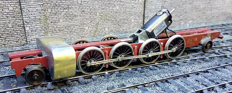
The cylinders and support bracket have now been fixed permanently to the frames. Note how the bracket slopes slightly forwards
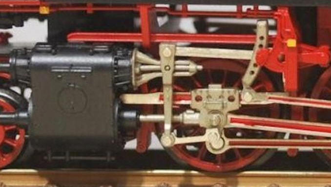
This is what the valve gear on a Fleischmann HO scale loco looks like. Can I assemble something looking like this?
The BR86 only has one side bar from which the piston rod is hung. I've used a slide bar from an Alan Gibson S&D 2-8-0. It is strengthened with a length of 0.7mm nickel silver wire and is soldered securely in a hole in the front of the cylinder.
One side of the valve gear has now been completed. Most of the rods were taken from the S&D 2-8-0 kit although several have had to be modified. It looks quite crude at this stage but paint and weathering will tone things down and allow everything to blend together.
The buffer beam and various parts on the cylinder front have been added. These are vey simple approximations as without complex castings it is impossible to represent these accurately. I have used small 'top hat' wheel bearings with wires soldered in place.
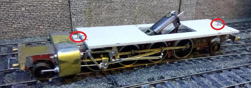
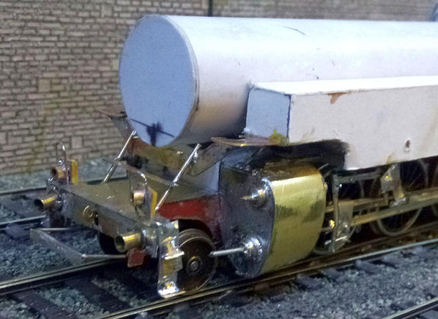
The basis for the body and boiler is this thick piece of card. It is supported on blocks made of several layers of card at the front and rear of the chassis which have nuts trapped inside the blocks and are held tightly in place by bolts passed through spacers in the chassis. The red rings show the position of bolts
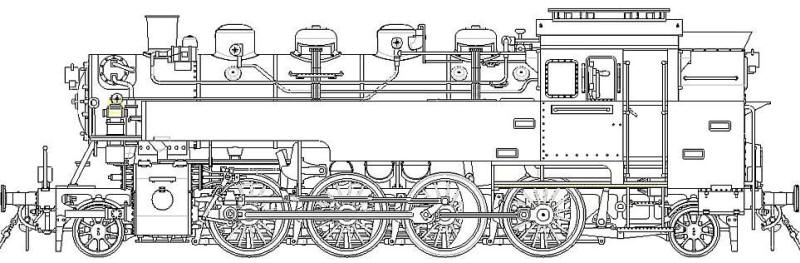
A drawing of the BR86 was found on the Internet and rescaled for S scale. This is the version with a large cut out at the front of the side tanks. I wanted the version with the much smaller cut out which the earlier versions of the BR86 had so only a smaller section of card was removed.
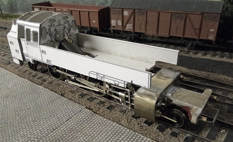
The side tanks, cab and bunker are now in place. Note the hole in the cab front which will give clearance for the possible later fitting of a fly wheel.
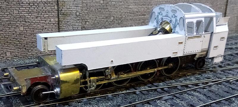
I've slightly modified the side tanks as they needed to be a few millimetres longer at the front.
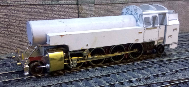
The flywheel has been fitted and the side tank inner sides glued in place together with lead sheeting to give weight over the driving wheels.
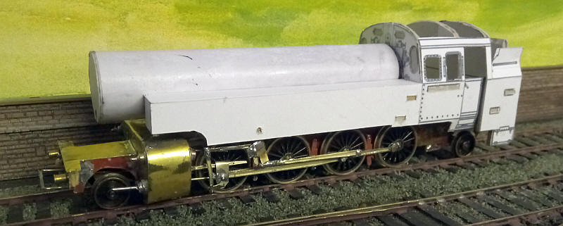
The boiler was made out of a length of plastic central hetaing pipe wrapped around with several lays of card. A slot was cut out at the firebox end to clear the motor and strips of card were glued on the base between the side tanks so that the boiler sits at the correct height.
The complex area at the front of the loco is now complete. The top footplate extensions are supported by brass wire bent to shape and soldered to the top of the cylinders and at the front by a bracket from brass sheet which goes under the boiler.. The headlamps are brass tube soldered to some copperclad sleepers strip and to a U shape piece of nickel silver wire which slot into holes drilled on the buffer beam.
A view of the loco at this stage.
The chassis has now been given a coat of black paint although some parts will be later repainted in red.
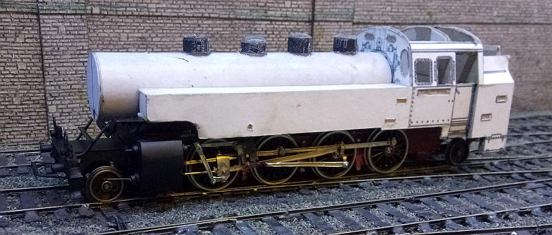
I've now added the various domes and sand boxes that are a feature of the BR86s. These are made from short lengths of tube that have been salvaged from old Staedtler overhead protection pens. Cut to the right length and filled with epoxy resin they are then shaped to give either a flat or slightly domed top. A short length of dress making pin is inserted in holes in the dome and boiler and is used to accurately position them. The top of the boiler is filed flat under the domes and they are then secured in place with epoxy resin which fills in any gaps.
The chimney on a BR86 is probably best described as a tapered stove pipe. To make this I took a length of brass tube and made four saw cuts about 7mm long at right angles to each other. The slots were then gently widened at the top. The four gaps were flooded with solder and then the surface filed smooth. The result is a slightly wider top and a resultant tapered chimney. A hole was made in the boiler top and the tube cut to the correct length so that it sits on the bottom of the plastic boiler tube.
The strange tube at the front of the smokebox is to represent the pre-heater that most German engines had. A slot was cut in the top of the boiler and the tube was glued in place. Small amounts of epoxy resin seal the ends of the tube.
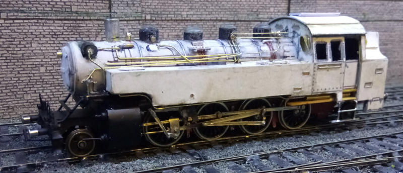
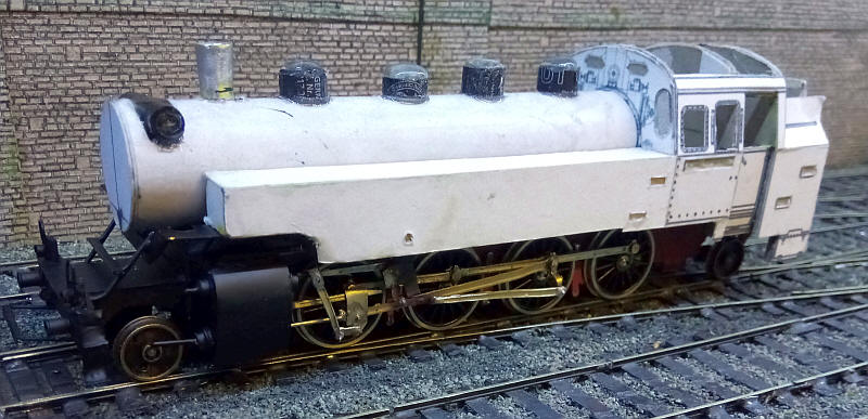
This photo and the three below show the completed model after the addition of numerous lengths of brass rod, microstrip and platic rod to represent the numerous pipe and cable runs on the real loco.
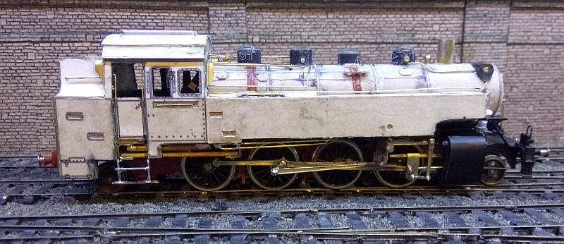
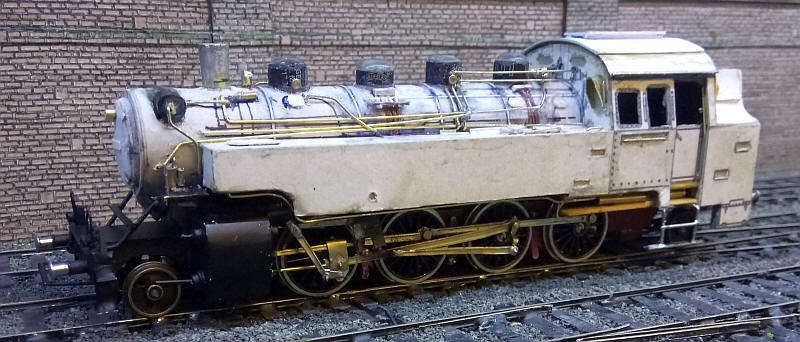
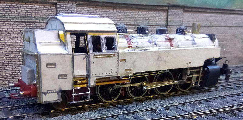
The chassis is seen painted to represent a reasonably clean locomotive as could sometimes be found even in the 1970s.
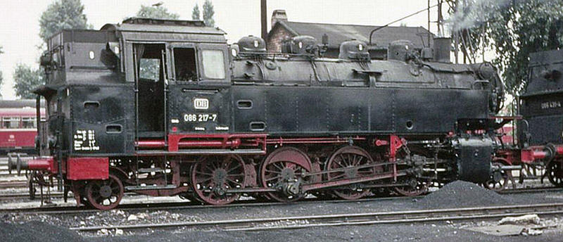
This is the real 086 217 (photo from website Dampflokomotivarchiv.de)
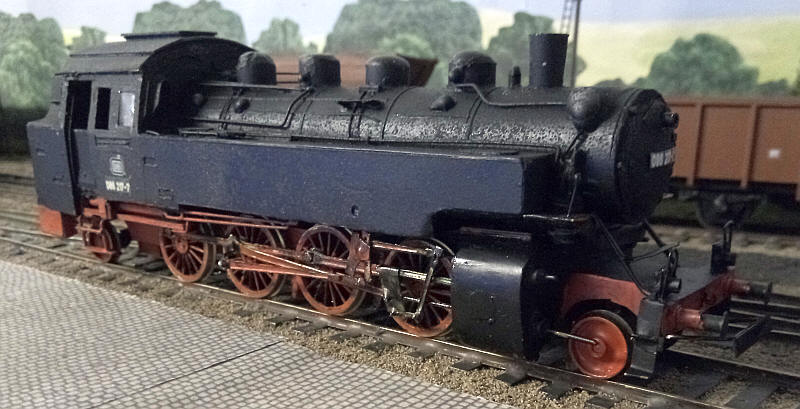
The finished model. Click here to see a short film of the loco in action.