Building a DB V60 0-6-0 diesel shunter
For my next German locomotive I've decided to build a model of the standard V60 diesel shunter.
A firm called HS Designs produces a superb card kit in O Scale which I've obtained and will build eventually as intended.
First, however, I've scanned the card sheets and reduced them to S Scale and intend to build a working model using the scans to build a card body.
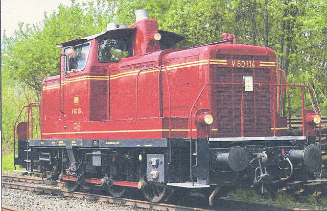
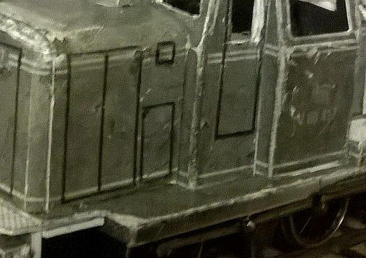
A photo of the original locomotive.
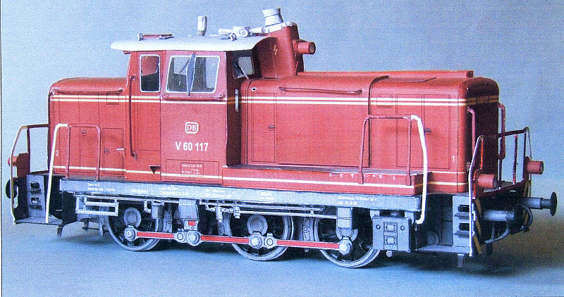
The O Gauge assembled model.
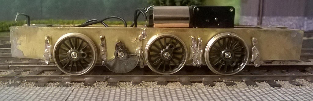
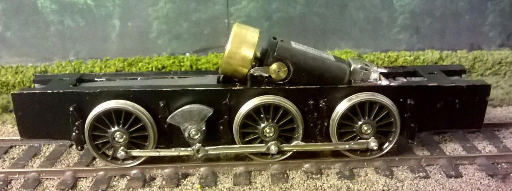
The first stage is to construct a working chassis for which I'll use the re-scaled kit to produce paper templates. The frame will be made from brass and I will use a RG4 motor and gearbox with Markits LMS 19mm driving wheels on S Scale axles which gives virtually a spot on size and number of spokes for the V60. Coupling rods will be Alan Gibson ones adjusted to the correct dimensions.
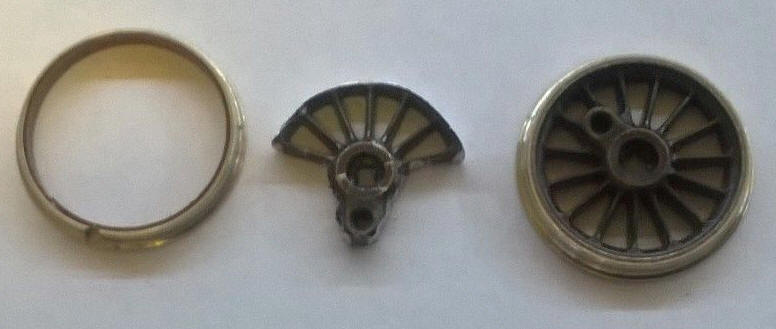
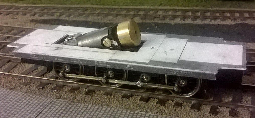
An essential feature will be the reproduction of the jackshaft. To do this I've taken one of the driving wheels and cut down to the required size. First the wheel tread is cut with a hacksaw which allows the centre casting to be removed. The unwanted spokes are removed by snipping them with side-cutters. The rough edges and the outer edge of the wheel are filed to give the correct shape and size for the jackshaft as in the photo below. The spokes were later filled with epoxy resin and the surface filed flush. The axle securing hole and crankpin hole are obviously untouched so when the coupling rods are added they should behave just like another wheel.
Using the printout for the loco frames I glued a print out of this onto a piece of 0.016" brass sheet. After cutting another piece of brass to roughly the same size I tack-soldered the together at the ends and filed the edges so that they are exactly the same size. Using a sharp point I made an indentation in the top layer of brass at the axle and crankshaft centre points as well as the six holes for the brake hangars. Then pilot holes were all drilled with the smallest drill bit I have.
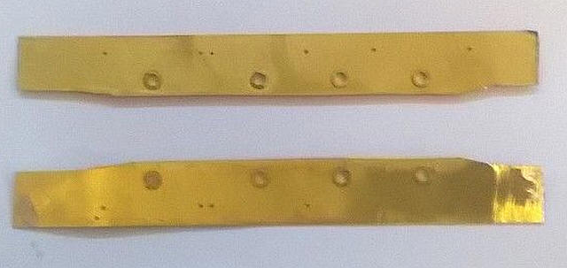
The pilot holes were gradually opened up using broaches until the axle holes were large enough to accept bearings as a tight fit.
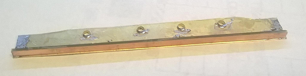
Because the brass to used for the frames was quite thin, and to ensure that the frames remained straight, I soldered a length of copperclad sleeper strip along the top inside edge of the frames to make what is in effect an L shaped girder. By leaving a slight gap between the top edge of the brass frame and the top of the sleeper strip there is also a locating point for the frame spacers.
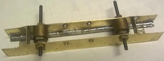
The frames were set at the correct spacing using frame spacers that bolt through the two outer axle holes. At this stage I've just added four spacers - two on the top which will act as locating points for the body and two vertical ones outboard of the outer axles to ensure the vertical alignment of the frames.
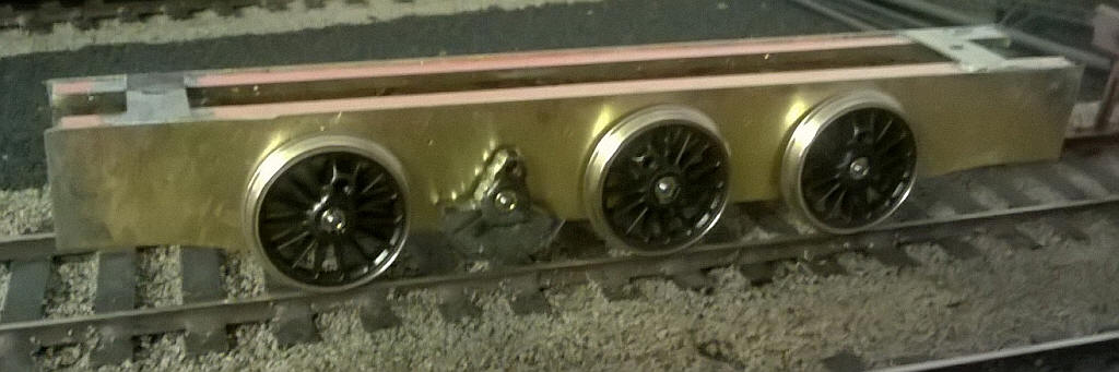
This is the wheeled chassis after fitting the frame spacers. The crankshaft is also in place.
Track holding when rolled around the layout is good.
A little more progress with the brake hangars and brake shoes added. The real loco has double brake shoes on each wheel but there isn't really space to fit them in especially around the crankshaft so I've decided to fit these right against the frames. Washers behind the crankshafts allow them to pass over the brake hangars without hitting them. The Portescap motor and gearbox fit perfectly in the space between the copperclad sleeper strips that strengthen the frames. The brake gear comes from an Alan Gibson Midland Railway loco fret.
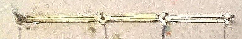
Using some coupling rod alignment jigs (which have sharp points at the ends) I passed these through the bearings and pressed down onto a piece of card, which was fastened to a piece of chipboard. This marked the centre points of each axle on the card and a moulding pin was tapped into the wood at these points to make a simple jig. The rods were made up by cutting and splicing spare coupling rods from Gibson kits. The front and rear halves of the rods were soldered together at the correct spacing.
The chassis is now operational. The coupling rods were fitted without too much trouble after the holes were opened up a little more with a broach. Using Markits/ Romford wheels quartering is automatic and all wheels were perfectly concentric with no wobbling.
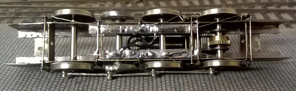
The underside of the chassis reveals the method used for electrical pickup. Copperclad sleeper strips have been soldered to the crosswires of the brake hangars. Insulating gaps were cut inboard of these to give an isolated section for securing the nickel silver pickup wires.
After lubrication, and a few minutes running in, the chassis runs very smoothly and when weighted will no doubt be even better.
I spoke too soon! The Portescap motor burnt out!
After completing the chassis I decided to give it the customary "run-in" on the bench. All seemed to be well so I left it running, seemingly quiet happily, only to return an hour later to find the motor burnt out and locked solid.
I had had my suspicions about the Portescap motor as, even using a non-feedback controller, it tended to surge. Anyway, the next day I decided to rebuild the chassis to correct one or two things that could be better.
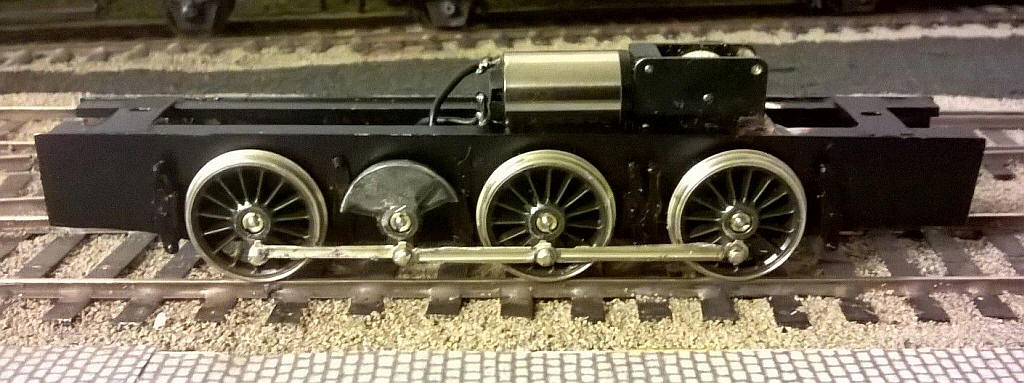
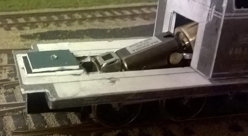
The motor has been replaced by a Mashima can motor fitted with a flywheel and driving through a Markits gearbox. I also decided to modify the crankshaft and trimmed off one spoke on either side and filed the remaining part of the rim down to just a sliver of metal.
I also decided to make the coupling rod between the centre and leading axle fixed rather than pivoting on the crankshaft. this was done by simply soldering the two sections of the coupling rods together. The crankshaft is now driven only on one side. A pin was soldered through the rod joint and simply slots into the crank pin hole in the crankpin.
Building the loco body
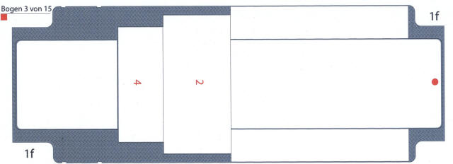
Construction of the body starts with assembling the running plate. This is formed of upper and a lower pieces which are glued together and then have a slot cut in the centre to allow the motor and gearbox to fit inside the body.
Upper side of footplate
Lower side of footplate
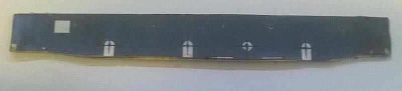
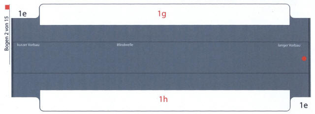
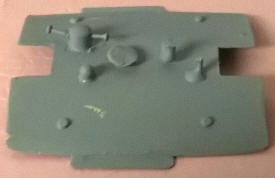
Underneath the running plate there are strengthening pieces which are intended to be folded up to make a cuboid. These are to be glued in place in the positions shown as 1h and 1 g.
For my model I used two 10mm wide strips of card glued inside the strengthening pieces. These were then glued in place as in the photo below.

The underside of the running plate with the motor hole and strengthening pieces in place.
The running plate assembly is loosely in position on the chassis.
The main part of the cab is a fold up assembly which went together perfectly.
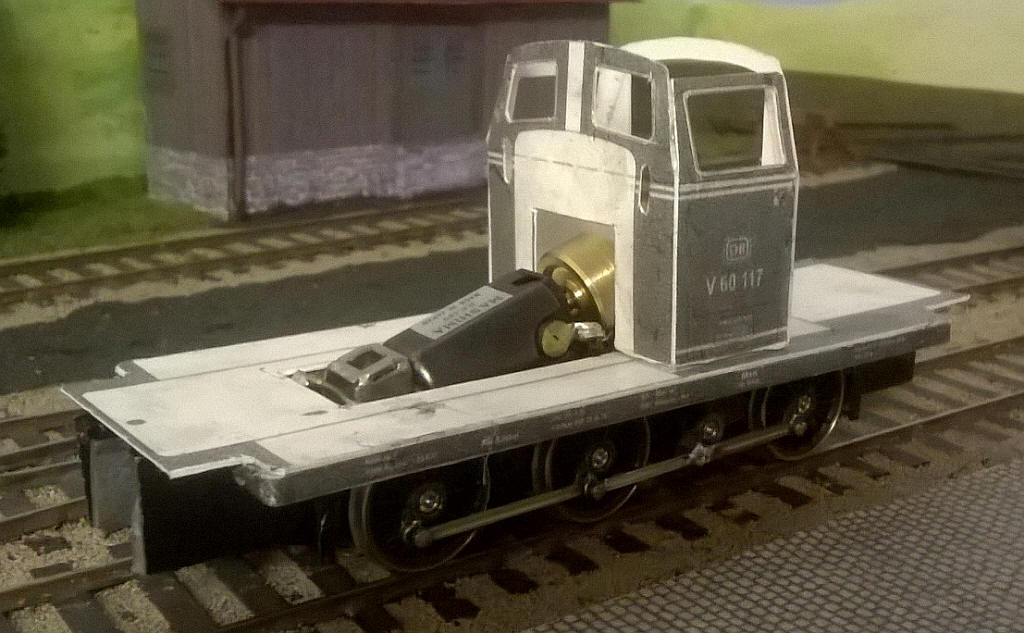
The main part of the cab has been cut, folded and stuck to the running plate. A slot has been cut in the cab front to accommodate the flywheel and I've cut the windows out inside the lines for the window frames.
The other half of the cab is narrower and includes the cab doors. At this stage the cab is extremely fragile.
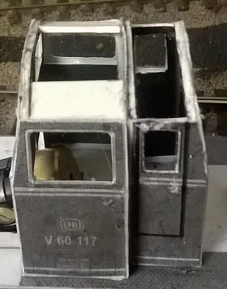
I glued the templates for the cab interior walls to a piece of 1.5mm thick mounting card and after cutting out the window openings slightly oversize I glued these inside the cab. Further pieces of mounting card were glued to strengthen the top and sides of the cab and door windows. This produces a good solid structure which will be even better once the card is hardened using petrifying fluid.
The body is held to the chassis with nuts and bolts passed through the front and rear spacers. The nuts are held captive in a slot cut in a rectangle of mounting card with a further layer on top to keep in place. The finished result can be seen above.
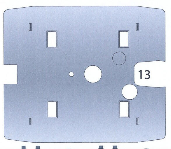
The next stage is to add the two bonnets on either side of the cab. The long side is shown below together with the end with the radiator on it and one of the internal spacers.
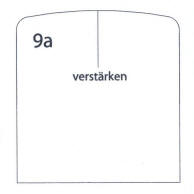
This stage is one of the more difficult parts of construction as the bonnet ends have rounded corners and the top of the bonnet has a curved profile as well.
I built the long hood in stages. The first step was to cut out the two main parts and carefully shape the card and then glue the parts together. I then cut a front internal spacer made up out of two layers of mounting card and filed its edges to give a rounded profile that will support the curved edges of the radiator end.
A piece of mounting card was then cut and shaped to a ' U' profile to fit inside the hood. This has to be cut and folded exactly the right size and shape. I was lucky first time on the long hood and now have a solid assembly.
I've now added the shorter bonnet which was built in exactly the same way as the longer one.
It's not really obvious in the photo but the corners of the cab have been slightly rounded by filing the edges.
The next step is to add the shutters' platforms, drag beams and buffer beams at each end. This means adding the chequer board plate in front of the bonnets and then using various small pieces of card as hidden reinforcements assemble the various parts. The buffer beam is folded up into a U shaped channel and pieces of mounting card glued inside it. This will give a firm basis for mounting the buffers.
Viewed from underneath a slot has been cut in the drag beam and 8 squares of mounting card have been glued behind it. This ensures that the beam stays vertical and will provide the support for the couplings which will be fitted after painting.
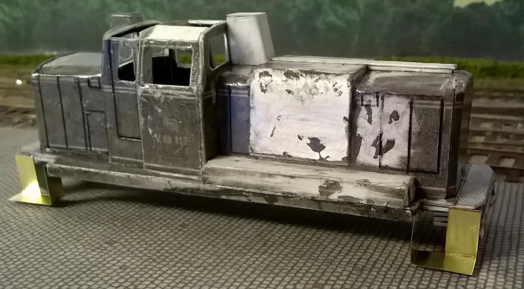
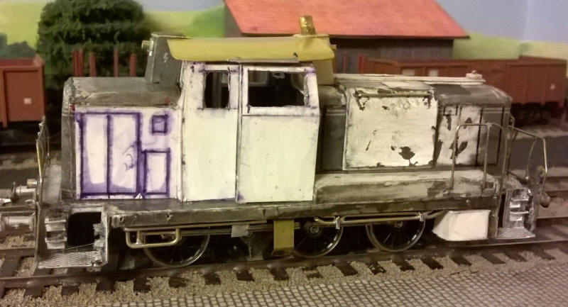
It's now a case of adding the remaining card components. On either side of the cab there are vertical casings. The one on the short side contains a small reserve fuel tank...

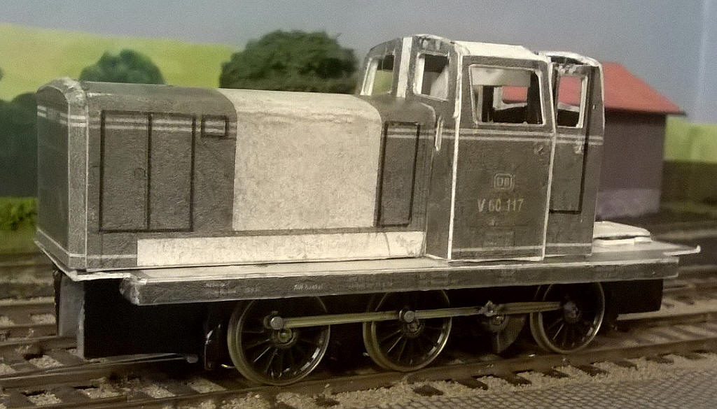
....whilst the larger one on the engine side of the cab holds the exhaust silencer. I felt that the shape of this part in the kit didn't represent the bulk of the real thing adequately (and was extremely difficult to assemble neatly when scaled down from O to S scale. The removable engine compartment cover has been shaped and glued to the bonnet. Various other components have also been added. The reason for the white colour is that one or two small patches of adhesive had been seen on the card so I used a fibre glass "pen" to remove them and, inevitably, the grey of the printer ink. The body will now be treated to a coat of wood hardener before moving on to constructing the metal shutters' platform steps and handrails.
The handrails and platforms at each end and corner of the loco which are used by the shunting staff are far too fragile to be made in card on a working model so I shall be using brass sheet and wire for these parts.
Although not apparent in the photo the card body has been painted with a coat of wood petrifying fluid. The card now feels almost like plastic.
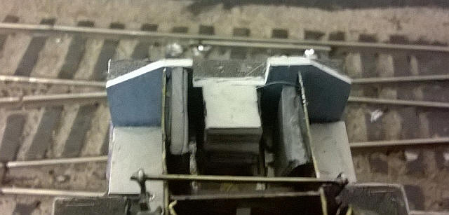
The basic shunting platforms have been attached and are made from thin brass cut with a heavy duty craft knife using the card parts as a template. After folding into the correct shape they have been attached to the loco's buffer beams and frame with epoxy resin.

Probably the part of construction that concerned me most was the handrails at the ends of the loco. The method I adopted was to use the card parts as a template and build up the handrails and the metal plates that contain the headlights on it. This was done by covering the handrails with double sided sellotape and soldering up the handrails on this. It requires fairly careful work but the results can be seen below...
The handrail unit was secured to the vertical parts of the steps with solder whilst the two centre vertical rails were bent at right angles to fit under the shunters' platform and will be secured with some epoxy. Then end result seems perfectly secure.
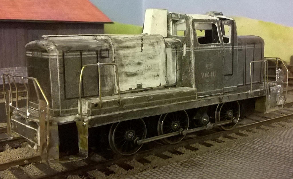
The handrails on the sides of the loco have now been fitted - they were bent to shape using the card parts as a template. I'm not too worried that the handrails aren't completely vertical - even Roco HO scale RTR models have floppy plastic handrails!!
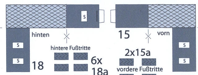
I decided that the steps on the shunters' platforms would use the card parts glued onto the brass. It's a clever design with small flaps (marked S) that are intended to be cut on three sides and folded out to form a support for the actual footsteps (parts 15/ 16 and 18).

As I'd already soldered the handrails to the base of the steps I also needed to separate the inner vertical pieces from the chequer plate and the outer vertical pieces. Once glued in place an additional piece of card was glued underneath the steps to give some extra support and then a tiny amount of epoxy was also spread under the steps to make the steps really rigid. I've now also added the buffers which are 4mm scale British Railways 2'0" heavy duty buffers by MJT and are very close in appearance to those used by DB.
The next stage was to add the cab roof. Using a paper print out of the roof in the kit I attached this with double sided sellotape to a piece of brass and using scissors and a craft knife (for score the recesses in the ends of the roof) I cut the brass with scissors.
The brass was bent to shape and also had some brass strips,(representing the rain shields) soldered along the edges.
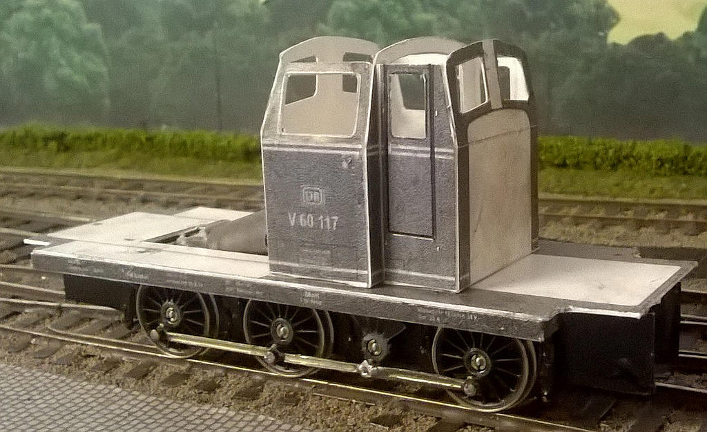
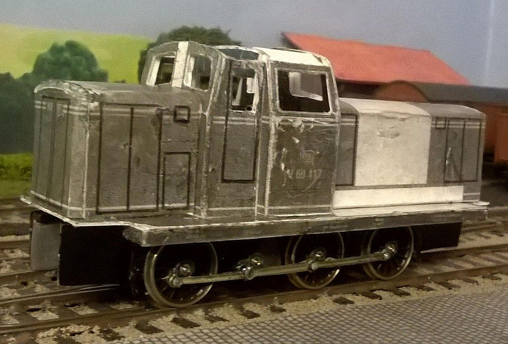
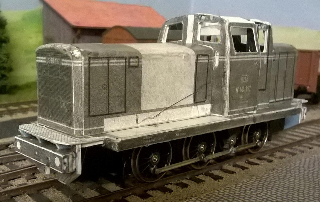
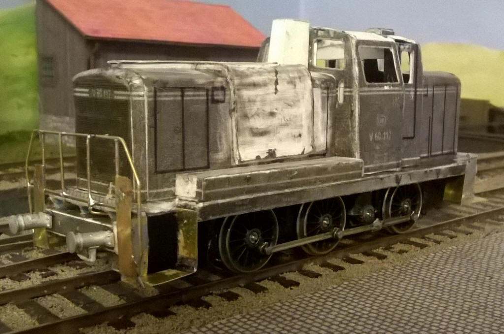
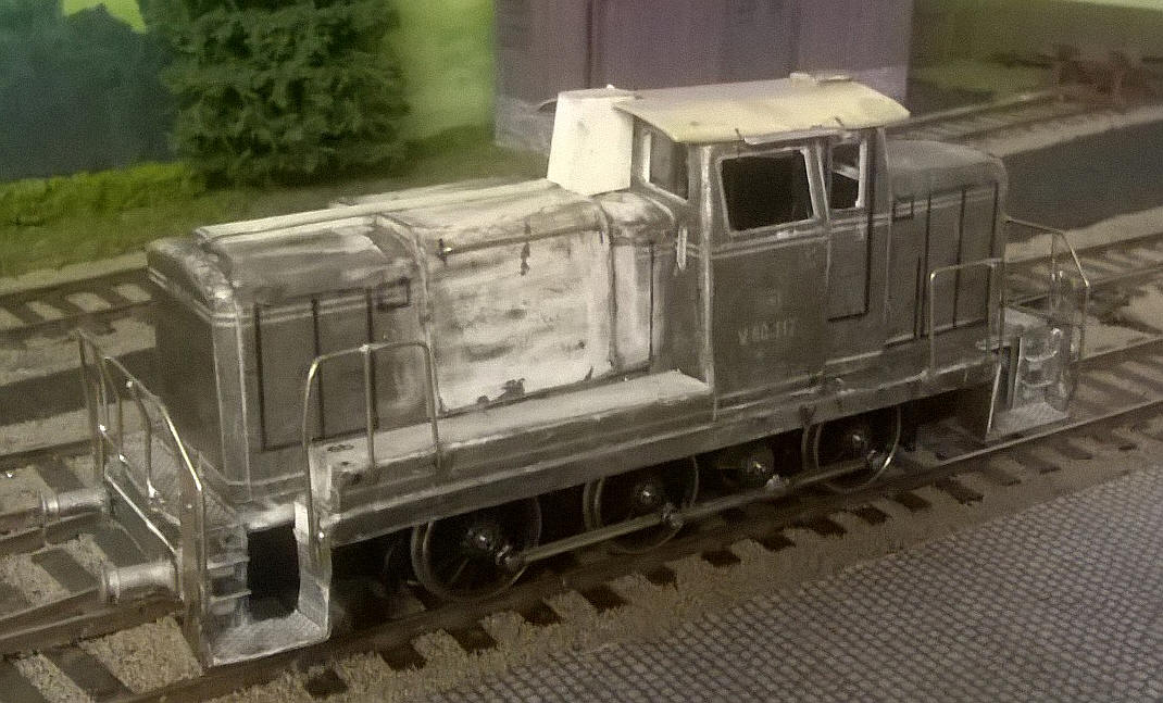
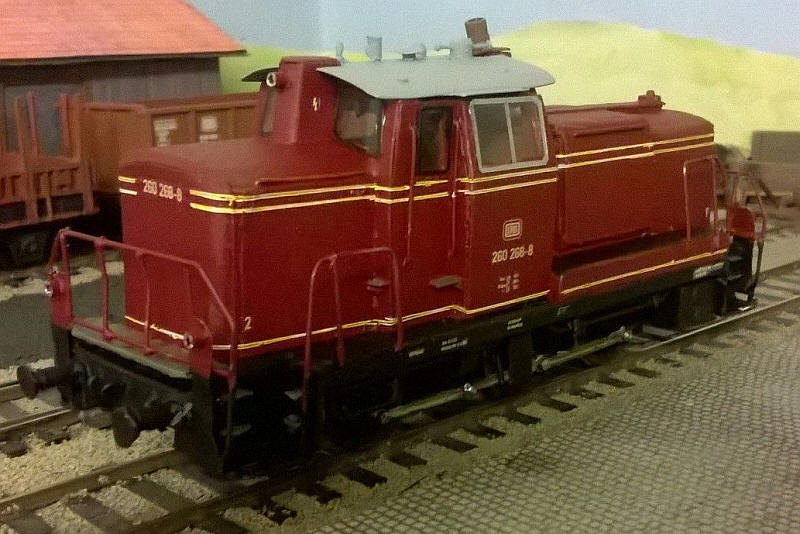
The model is beginning to look like a V60 at last.

The exhaust outlet is in place - a piece of brass tube cut and filed to shape - and the two top headlights have been added from small brass tubes. The frame for the front engine grill is in place from plastic strip.
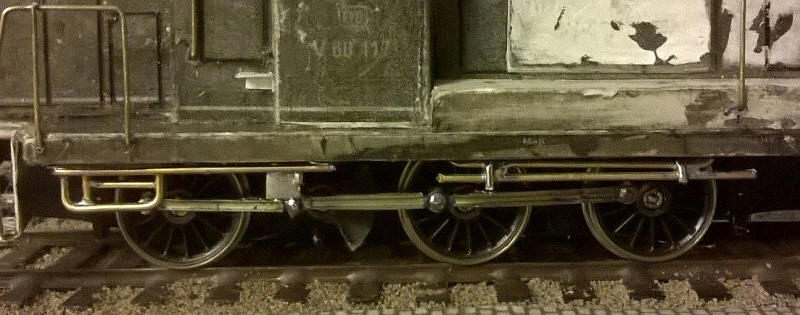
The very obvious pipework under the footplate was soldered up from 1mm diameter brass wire and held in place wither by being plugged into holes in the cardboard or soldered to brass sheet which was the secured to the underside of the footplate with epoxy resin.
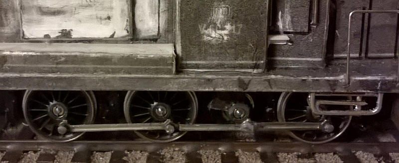
At this point something that has been concerning me for some time came to the fore. On the right hand side of the loco the cab and rear bonnet were not located quite correctly. A series of tiny errors meant that the cab and bonnet sides were not exactly parallel to the running plate edges as can be seen in the photo above. I think there must have been some errors in the re-sizing of some of the parts of the pdfs.
At first I thought I could accept this but in the end I decided I would have to correct the error. Narrow packing strips a few millimetres wide were fitted to the original sides at the ends of the cab and bonnet that were too far away from the edge of the running plate. New cab, door and bonnet sides were then cut from thin card and glued in place.
As can be seen the sides are now parallel with the edge of the running plate.
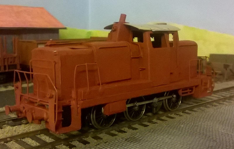
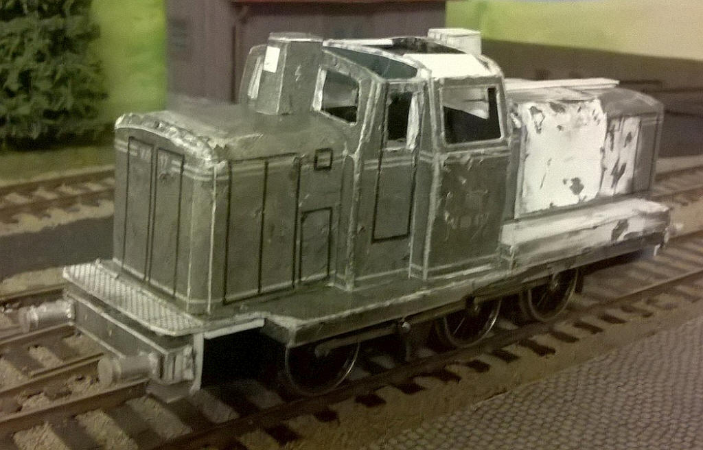
The loco is now complete apart from the various details needed to be soldered onto the brass roof. Spraying it in primer brings the various materials and together.
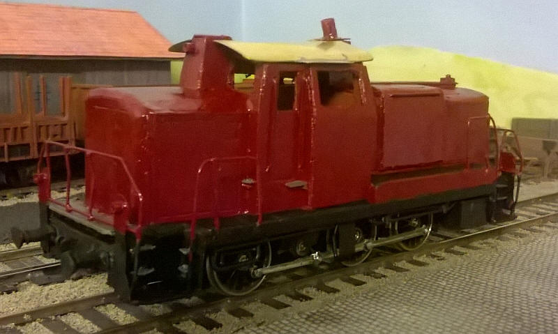
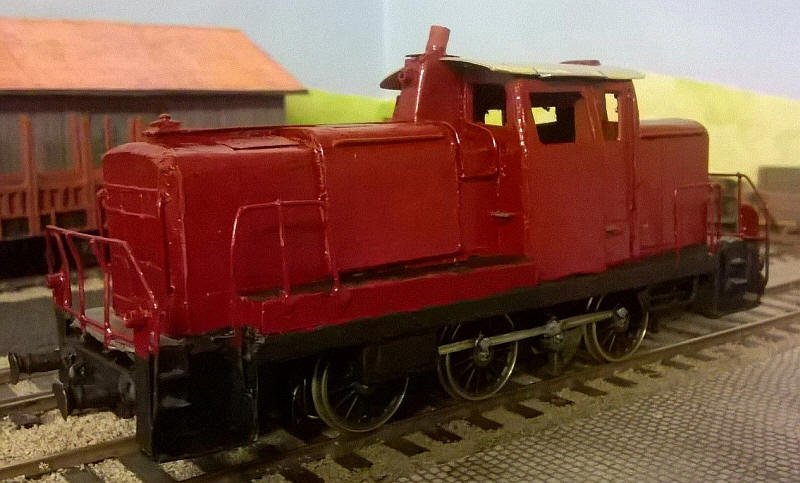
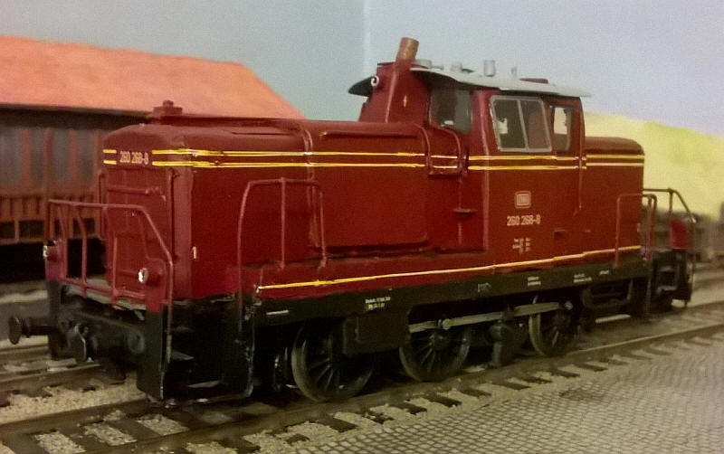
The model has now been painted in DB purporrot (Humbrol No.20 paint)
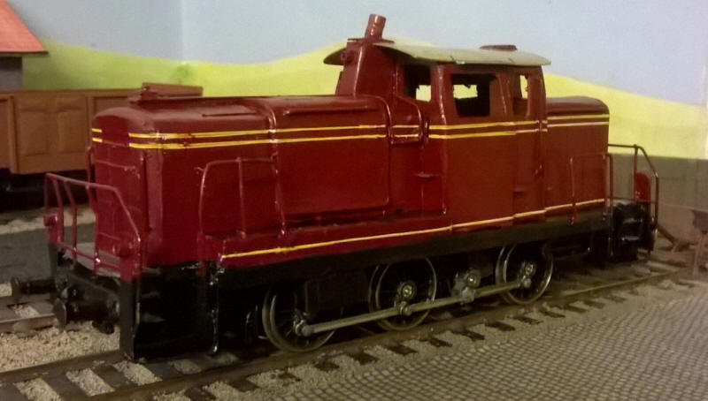
The next problem to be solved was how to line out the model in the rather complex way that DB used for locos in the 1960s and early 1970s.
The method I chose has given a reasonably close result, although by no means perfect.
The Historical Model Railway Society (HMRS) produce rub-on lining transfers for British Railways carriages. Among the various transfers on the sheet were the narrow white lines used to separate the grey and blue painted sections of carriages in the BR blue period. On the transfer sheet these give a constant distance between the lines if two parallel lines are applied together. Unfortunately, they are too far apart. However, I decided if I applied the two lines first and then overlaid these with another transfer positioned below the first set of lines an acceptable result could be obtained. The lines would therefore be slightly thicker and the gap between them slightly smaller.
The lines are of course white, but a Staedtler overhead projector permanent marker pen is available in a creamy yellow colour and can be used to colour the lines after they've been secured in place with spray varnish.
The roof has had various details added - the cab ventilator, radio attenae, bell and horn. All have been fabricated quite crudely from pins, brass tube and dics with solder and epoxy resin being used to secure and shape.
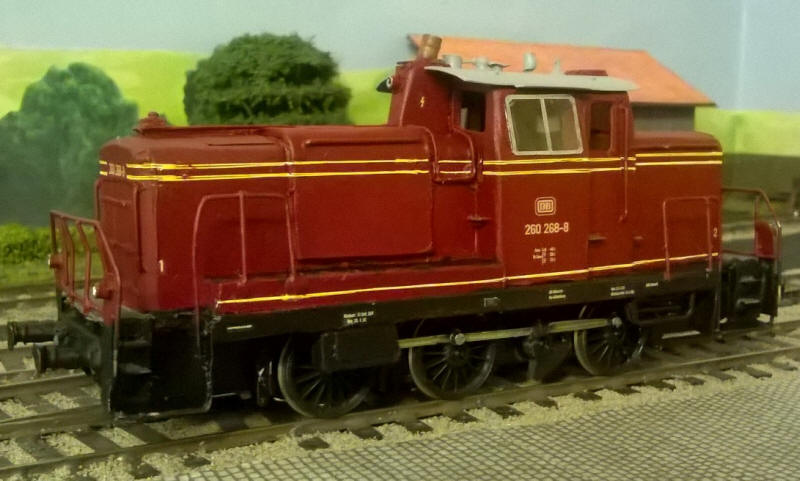
The lettering comes from Modellbahn Decals again. Andreas Nothaft provided me with custom numbers for a computer numbered BR 260 at no extra cost and supplied them within three weeks of my order. Highly recommended! See his website at http://www.modellbahndecals.de.
The cab windows are simply a sheet of thin plastic glazing material with the silver frames drawn on using a Pilot fine nibbed permament silver marker pen. The windows are held in place with a tiny amount of epoxy resin smeared along the edges of the window opening on the cab side.
All that remains to be done is to add the balance weights to the wheels and a driver in the cab.
THE LOCO IN ACTION
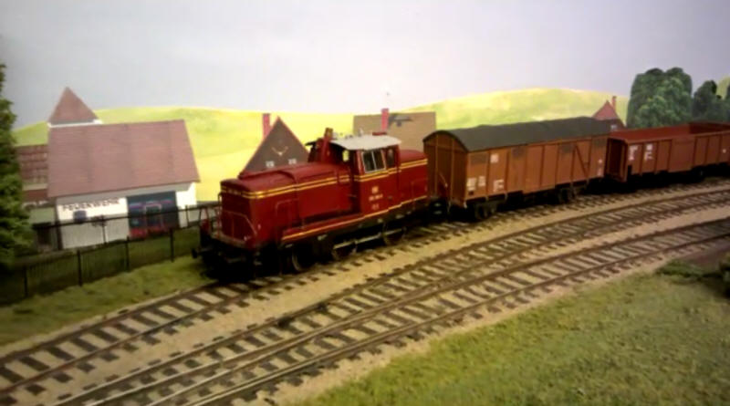
Click on the photo to see a short film of the loco in action