BUILDING A JOHNSON 2-4-0
For some time I've been thinking it was time to completely scratch build a locomotive now that my skills have developed. The chosen prototype for this is the Johnson 2-4-0, a locomotive for which I have a particular soft spot. It was a Ratio 4mm scale plastic kit which launched me on my locomotive building career. It didn't run very well due to the somewhat curious combined brass and plastic chassis but it certainly looked rather appealing sitting on my layout.
Having built a Johnson 0-4-4T and a Kirtley 0-6-0 using Alan Gibson's frames I've decided that I really must try my hand at producing a locomotive completely from scratch. There's no need of course to build the tender since I've got a spare etching of one of Alan's Johnson tenders. However, the locomotive itself will be completely my own work. There's also the possibility that I might build an alternative tender. Whilst some of the 2-4-0s ran with the larger 3,250 gallon tender many more used the 2,950 gallon version.
As is usual I shall be employing some unusual methods of construction and these will certainly extend to the frames!
Experience with my Kirtley 0-6-0 suggests that one way to build frames is to photocopy a scale drawing of the locomotive and glue this onto brass sheet to act as a template for drilling holes and cutting the brass. Thus I adopted the same method for the 2-4-0. I'd found a suitable photocopied drawing and simply drew a line along the visible lower parts of the frame as well as extensions to represent where the springs and ash pan were. At the top I drew a further line allowing for the thickness of the running plate. The holes for the driving axles would have been very close to this so I drew in an extension above the running plate level, which will be hidden behind the splashers.
This template was then cut out of the original photocopy and glued to the brass with Pritstick. I marked the centres of the driving axles as carefully as I could and used a compass point to press into the brass. Next very small pilot holes for the three axles were drilled .
The brass was cut out around the template using my trusty large pair of scissors, with any tendency to curl or have rough edges being dealt with using a file. I then tack soldered this first frame to another piece of brass, re-drilled the holes using the first frame as a guide. I progressively increased the size of the holes by drilling with larger bits until I could insert a broach into them. I then drew the outline of the frame onto the brass with an OHP pen and unsoldered the joints. The second frame was then cut out taking care to cut on the inside of the line.
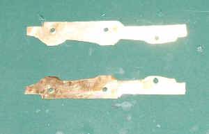
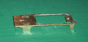
The two frames ready for assembly
The assembly of the frames followed the usual steps as below:
Axle holes opened up progressively with a broach to accommodate 1/8th inch top hat bearings which were soldered in place.
Using frame spacing jigs (produced by Comet Models) and some washers as additional spacers to give the correct spacing for S Scale I bolted the two frames together. Some spare frame spacers from Alan Gibson and Worsley Works were then soldered in place in various locations, allowance being made for future fixing points for the locomotive body.
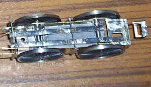
After test fitting a pair of old driving wheels I was pleased to see that the chassis sat squarely without any need for adjustment.
Fitting the leading 4ft 3" diameter wheel proved interesting! I'd hoped I would be able to simply fit it into a bearing at the correct height so I opened up the axle hole vertically to allow some vertical play for the bearing which I intended to solder in place. I tacked soldered these in place and soon discovered that the wheels had a distinct tendency to derail.
The solution was to remove the bearings and solder them onto two lengths of springy brass wire. These were then soldered onto one of the spacers. The leading axle was passed through the bearings and the problems was solved. The obvious tendency of the spring effect to lift the leading driving wheels off the rail was cured with some weight. The basic chassis could be propelled around the layout using a one of my powered Johnson tenders.
At this stage I also used some London Road jigs to make the coupling rods. The rods were made from some spare 4mm roads soldered up with the joints in the front and rear layers overlapping (see the pages about scratch-building the MR 0-4-4T for details).
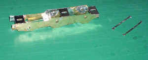
The basic frames with sprung bearings for the leading axle
(it is an optical illusion that the bearings are not opposite each other).
Holes were then drilled for the brake hangers and, once again, I raided my box of left over etchings for suitable ones from an Alan Gibson kit. The inside of the chassis was packed with lead and paxolin sleeper strip soldered to the brake cross wires ready for fitting pick-up wires. A rudimentary rear tender coupling was soldered to the rear frame spacer.
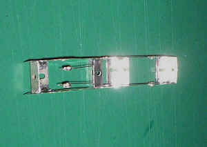
The free rolling chassis now awaits painting
The next task was to begin on the locomotive body. I started off by marking out on a sheet of brass the rectangle for the running plate. This needs a large hole cutting in it to accommodate the driving wheels and two smaller holes for the leading axle splashers.
These small holes were cut out first by drilling a series of small holes and then using a small chisel blade to break through the brass - brutal but quick. The ragged edges were dressed with a file.
The main cut out was made using my scissors. I had intended to saw the metal but in the end reverted to my bad old ways. My excuse is that I wasn't very well at the time and didn't want to have to go out in the garage to use the vice. I should have known better because naturally enough the brass curled up and I had rather a lot of trouble persuading the metal back flat. I ended up having to solder some temporary strips of nickel silver in place to make the whole running plate lie flat. Next time I'll do it properly...............
On the 2-4-0 the valance that runs underneath the locomotive's running plate incorporates the axle boxes for the leading wheels. These two pieces were marked out using the photocopies as guides and cut out with scissors again. These were easily persuaded to revert to being flat with pressure on both sides from a file. One of the nickel silver strips was unsoldered and a brass valance soldered in place allowing just a small overhang of the running plate. The process was repeated on the other side. I then filed the inside of the running plate back towards the valance to give a 31mm width which should be sufficient to allow the coupling rods to move without fouling the metal.
A rear drag beam was fitted together with a rather basic wire and slot tender to locomotive coupling. Two holes were drilled for fixing bolts which line up with the holes in the front and rear spacers of the chassis.
 |
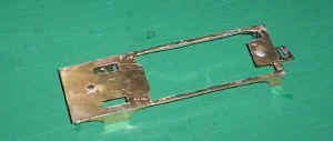 |
The basic structure of the running plate and side valances.
Oh dear! Upon test running with this new part of the locomotive I ran into a big problem. The coupling rods and crankpins kept hitting the inside of the running plate. I'd forgotten two essential things. the first was that my wheels, being EM profile a somewhat wider than scale. the second was that the crankpins and coupling rods are also considerably over scale. At first I couldn't see anyway around this problem but in the end I realised that if I want a Johnson 2-4-0 to run around the tight curves of my layout then compromises are going to be necessary.
The compromise is simply that the running plate needs to be about 2.5 mm wider, or roundabout a scale 6 inches, than the prototype. Now this is a bigger compromise than I really wanted to make but given the choice between a rather tubby locomotive and none I've decided to accept the compromise.
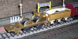
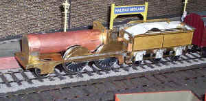
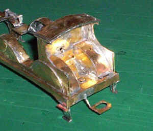
I decided that rather than start all over again, I'd see if I could splice in a strip of brass down the centre of the running plate. I unsoldered the drag beam at the rear and cut the running plate down the centre line. A strip of brass about half an inch wide was soldered to the underside of one of the two halves overlapping sufficiently to be able to bridge the gap. A second strip, about 2.5mm wide was soldered to it making sure that there was no gap between the running plate and the insert. Finally the two halves were soldered together and the narrow gaps on top of the running plate were filled with solder and files smooth. A buffer beam was soldered in place and a modified drag beam and cab footplate were soldered back in place. The photo below shows the appearance of the model so far.
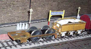
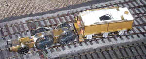
The complete rolling chassis at the head of its first train -
the advantages of a tender drive unit are obvious here!!
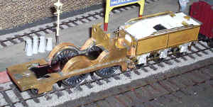
Test running revealed that the leading axle still had a tendency to derail caused, I suspected, by the sideways friction of the inside sprung bearings. I unsoldered these and immediately the problem disappeared. The axle is free to move up and down in the slot in the main frames and also has a little lateral side play. The two springy wires keep the wheels firmly on the track and the "locomotive" runs confidently over even the tightest curves on the layout.
Now for the boiler and cab assemblies!
Splasher and cab sides
Using the resized drawing of the locomotive as templates I cut out the brass sheet for the cab sides and splashers as one piece, and then filed to shape as needed. The axle centre points were marked on the running plate and the splashers and the two parts soldered in place. As mentioned earlier, the cab will be about a scale 6" to wide but I'm just going to have to live with this given my need for the locomotive to traverse 3' 6" radius curves and have sufficient sideplay. I suspect once in use on the layout the visual problem will not be over significant unless I view the locomotive head on.............!
The front of the cab was made in the same way as for the Kirtley 0-6-0, although I obviously had to make it slightly wider than scale.
NOTE: It wasn't until much later that I realised I had made a big mistake. In the diagram I was using the splashers had an almost flat section between the two large curved parts. As originally built this was indeed the case but, by the time I was modelling in the early 1920s, this had been altered to give a more elegant curved lower section. How I came not to notice this, given the number of photographs I'd looked at I don't know!! However, as you will read later I was able to put this error right.
The cab front soldered in place
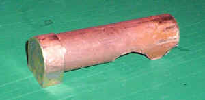
And so, on to building the boiler. I basically followed the same construction methods that I used for the boiler of the Kirtley 0-6-0. A length of copper central heating pipe was cut to the correct length with a 12mm extra section being used for the smoke box. Two cuts were made in the boiler to allow representation of the lower part of the round top firebox with its near vertical walls.
For the front of the smoke box and the smoke box saddle I soldered on a piece of brass and then cut and filed this to shape. A small piece of brass was cut to act as the rear of the smoke box saddle and was soldered on with great difficulty. Copper tube is notoriously to solder to especially when there are several layers! Finally two small pieces of brass were soldered either side of the smoke box to represent the sides of the saddle. The top inside edges of these pieces of metal were filed to a sharp tapered edge to allow a tight fit against the smoke box. Once a filet of solder had been applied and filed to shape the joint is unnoticeable.
Securing of the boiler to the running plate and cab was slightly different to the method I used on the Kirtley. At the cab end I used the same fixing method with a piece of brass being soldered to the end of the firebox and then filed to its profile. A bolt was passed through the front of the cab to hold it in place at the correct height. At the front of the boiler I've used a self tapping screw which passes through the running plate and into a hole drilled through the bottom of the smoke box.
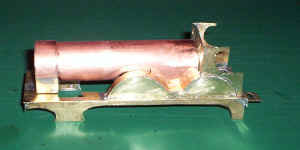
As can be seen in the photograph large chunks of the lower part of the boiler had to be removed to give clearance for the driving wheels. This was done by repeatedly marking where material needed to be removed until sufficient was obtained. It is obviously essential not to remove to much, otherwise there will be gaps between the top of the splashers and the boiler.
The completed boiler unit
The first impressions are that the basic proportions will be correct
(excluding that over scale width of course)
The next step was to remove a section of the running plate behind the smoke box saddle. I'd deliberately left this in place earlier until I was exactly sure where the boiler was going to be secured at the front. It was the work of five minutes to make three saw cuts to remove the metal. I've thus got an open space between the frames should I ever decide to fit a representation of the slidebars and connecting rods between the frames.
I now came to part of the construction that had been worrying me; the intricate curved tops of the splashers. In actually fact it was the work of less than half an hour to cut some strips of thin brass about 5mm wide and solder these in place hard up against the boiler and fire box. Obviously the boiler was removed to facilitate this but I was delighted and amazed to find that the boiler fitted tightly between the two tops and the only tweaking necessary was to bend the lower part of the fire box walls slightly outwards.
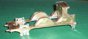
The splashers and the section of running plate that was removed
.
The locomotive is actually beginning to look a little like a Johnson 2-4-0
One of the other things about the construction of the locomotive that had been bothering me was the curved beading that is so prominent on the side of the cab. All sorts of ideas, some quite ridiculous, had occurred to me but I kept coming back to the idea of soldering brass wire in place. In the end it was surprisingly easy.
I first tinned the side of the cab where the curved beading is, then bent some wire to the correct radius and after tinning this as well soldered the wire in place a little at a time. Once the section on the flat part of the cab was secured I repeated the process soldering a little at a time to the top of the splashers. I used just one length of wire with no breaks bending it with either fingers or pliers as appropriate. I was careful to use as little solder as possible to minimise cleaning up with needle files and fibre glass pen. To produce the flat beading effect I simply filed the wire to give a level strip of metal.
The beading can just be seen in this photo. Another challenge overcome!
From now on construction of the locomotive becomes more a question of detailing with the really heavy work largely over. Attention turned first to the cab area. I first used some scrap etching strip to represent the beading around the cab openings and at the same time added the vertical handrails, securing these in holes drilled through the running plate.
The curved splashers dominate the inside of the cab both in real life and, even more so, in model form. Once again, I've had to make them wider than scale to allow for my over width wheels and sideplay. The photo shows that I cut some semi-circular pieces for the sides of the splashers, soldered them in place and then made curved covers. A false floor and lower cab front was cut and bent to shape before soldering in place.
The cab roof is simply a piece of thick brass cut to shape and soldered in place. Rain strips, from brass wire were soldered along the rear and side edges, and filed flat on top.
My dreadful soldering is painfully apparent in this photograph.
It will be cleaned up before painting!
Turning to the front end of the locomotive Alan Gibson buffers were added to the bufferbeam, being mounted, like on some of my other locomotives, on blocks of 4mm scale copper clad point timbering sleeper strip. The small splashers over the leading axle were added next - a strip of brass curved to shape completed the top.
Strips of scrap brass were soldered in place for the cab footsteps as well as the two small step like protuberances on either side of the leading axle box. For the prominent springs above the leading axle I used the springs and hangars from Alan Gibson's tender axle box castings secured in place with low melt solder. Likewise the axle box covers, modified slightly, came from the same source.
Front end details
This concludes the soldering construction with all further additions being secured with epoxy or super-glue.
Handrails, ejector pipes, vacuum brake pipes, lamp brackets were added and holes opened up in the boiler for the chimney, dome and salter valves as well as the safety valve covers. See the pages about building the Kirtley 0-6-0 for more details of how I do this. The boiler was then fixed permanently in place using epoxy and screws - some epoxy applied to the firebox end filled a slight gap between it and the cab front. A Gibson brass smoke box door was fitted to the front of the smoke box.
As you will have read earlier I made a significant error when constructing the locomotive's splashers so at a very late stage in construction I had to indulge in some careful re-building of the splashers. This discovery was made just after I had fixed the boiler in place which made my error even more irksome.
First I cut through the wire beading and removed about half an inch of the wire at the lowest point. I then flooded the flat top of the splashers with solder to round of the slightly angular bends. Finally I bent and carefully cut exactly to length a new piece of wire to fit in place. After soldering in place and very careful work with needle files and a fibre glass pen the joints are virtually invisible and the locomotive now has the correct profile of splashers.
Next time I will really have to pay more attention!!
The locomotive now has the correct splasher profile and most of the detail parts and boiler furniture are now in place.
The next two jobs on the locomotive's body were the fitting of a representation of the boiler controls and firebox in the cab. This was simply a semi circular shaped piece of thick plastic with a few pieces of plastic micro-rod and strip to represent the various bits of pipe work and regulator. As the loco crew will largely conceal this detailing is basic. A length of brass tube with a wire handle (to represent the reversing gear I think) was soldered to the right hand side splasher in the cab.
The prominent crankpin splashers were cut from 40 thou plastic sheet. I used solvent to fasten a photocopy of them onto the plastic, drilled holes at the corner of the "see through" section and then carefully cut out these very fiddly components. Inevitably, they aren't exactly the same size or shape. I simply super-glued these to the main splashers.
The final job to the body before the final cleaning and application of primer, was to apply some self adhesive PVA tape to represent the boiler bands. A couple of dabs of super glue were applied where the bands met under the boiler.
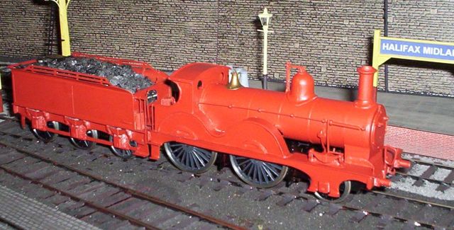
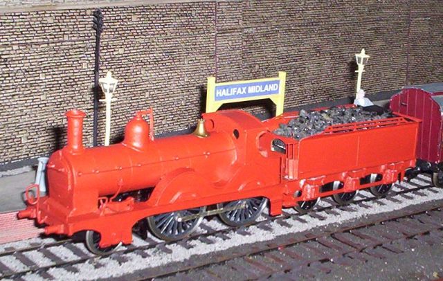
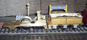
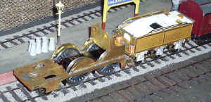
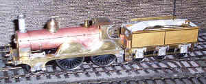
Two views of the completed body - the buffer heads will be fitted after final painting.
The front coupling and guard irons still need fitting to the loco chassis.
 |
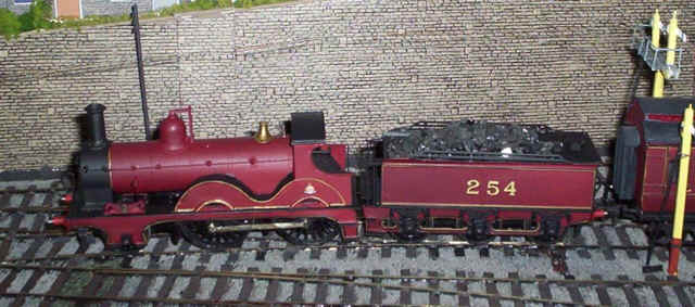 |
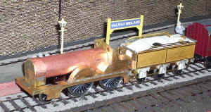
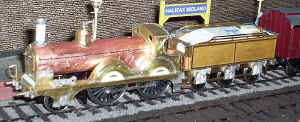
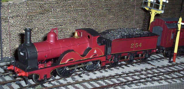
The locomotive after painting and hauling its first train to Leeds. The front coupling bar and loco crew are still to be fitted.
The smoke box door number plate was made on the photocopier using photos of different numbered locos stuck together and resized. Painting and lining was in exactly the same manner as for all my other locomotives using a Pilot gold marker pen and a very fine overhead projector pen. It's crude but, after reading other's thoughts on consistency I think it's better to stick with the method that I've used for all my locomotives and carriages. Perfection; I'll leave that to others.
So Halifax now has quite a fleet of locomotives:
0-4-4T
Kirtley double-frame 0-6-0
3F and 4F 0-6-0
Johnson 2-4-0
Johnson 483 4-4-0
Deeley 990 4-4-0
Deeley Compound 4-4-0
Under construction with only tender needing to be built is a "H" boiler 1738 4-4-0
Do I need this many locomotives?!!