BUILDING A KIRTLEY 0-6-0
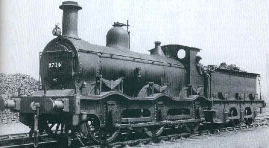
After weeks of prevaricating I've finally started scratch building another locomotive for Halifax. To be totally honest I'm intending to use a few bought-in components, including the main frames, so whether this model will count as scratch built depends on your point of view!! The chosen subject is a Kirtley double frame 0-6-0 with the curved footplate. Originally, I'd thought of building the straight footplate variant (as it's easier) but the photograph below changed my mind. It's of No.2714 from Leeds Holbeck (The MR Society's shed allocation list confirms it was there in 1920) and is photographed at Agecroft shed in Manchester, presumably after bringing in a freight from Carlisle or Skipton via Blackburn. By modelling this locomotive it will fit in perfectly with any MR layout based north of Leeds.
The plan is to build the locomotive in my normal style with a tender drive unit and a free-running locomotive chassis. Alan Gibson has supplied me with the frames from his 3F kit, which have the correct wheelbase, but will need shortening at the front and rear ends. Alan's 5' 3" wheels (with EM profiles), outside cranks, coupling rods and frame spacers are also being used.
Wild Swan Publication's book "Midland Engines No.4 The 700 Class Double-Frame" provides the essential diagrams.
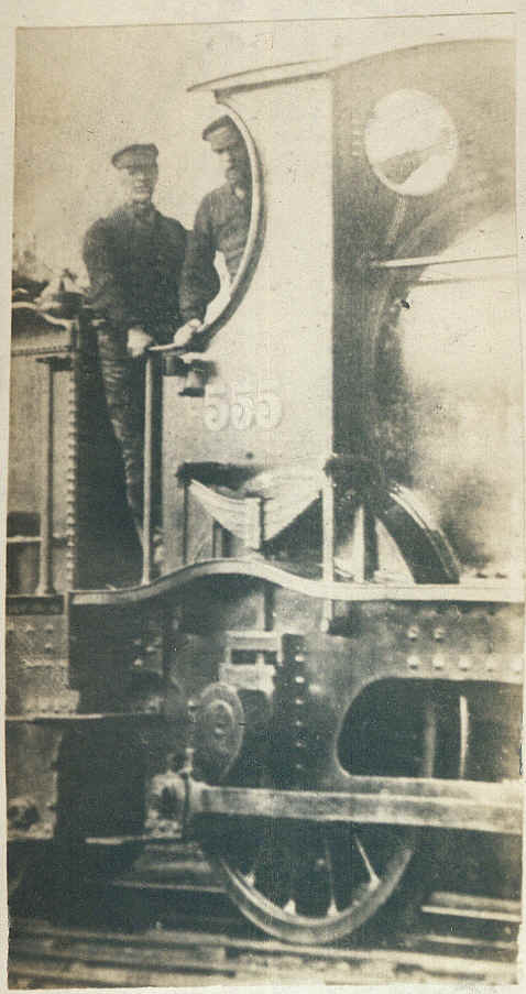
This photo probably explains why I'm so fascinated by the Midland Railway.
It shows my great-grandfather on the footplate of MR No.555 at Lancaster Green Ayre shed some time in the late 1890s.
He also served on the Midland at Birmingham and Sheffield shed.
Construction begins- the locomotive
I decided that unless I was capable of producing the outside frames in metal the whole project would not be feasible. Now my metal-working skills are almost non-existent but within two hours of starting the first frame side was complete. The second one took less than an hour! The first step was to photocopy the diagram from the book and reduce it to S Scale. I cut out the resulting "paper frame" and stuck it onto a piece of scrap brass from an etched kit.
At first I wasn't too sure about how to cut out the holes in the frame but decided that a series of small holes drilled a millimetre or so away from the inside edge of the opening would be a good start. I then used a heavy duty Stanley knife to cut through the brass between the holes and pushed out the scrap leaving a rough hole. All that I had to do then was file the brass to the shape of the hole on the paper. I have to confess I made a slight error and over filed in one corner but a touch of solder restored the metal here.
Then using my trusty scissors I cut that lovely curly top to the frame, as well as the ends. Finally I made one long cut across the bottom . To provide space for the axles and cranks I opened out the space between what, I presume, are the horn block guides. Five small holes drilled across the top, two lines scored across these back and front, two vertical scissors cuts and, with a quick wiggle with a pair of pliers, out fell the brass. A couple of swipes with the file at the top and there were now three openings.
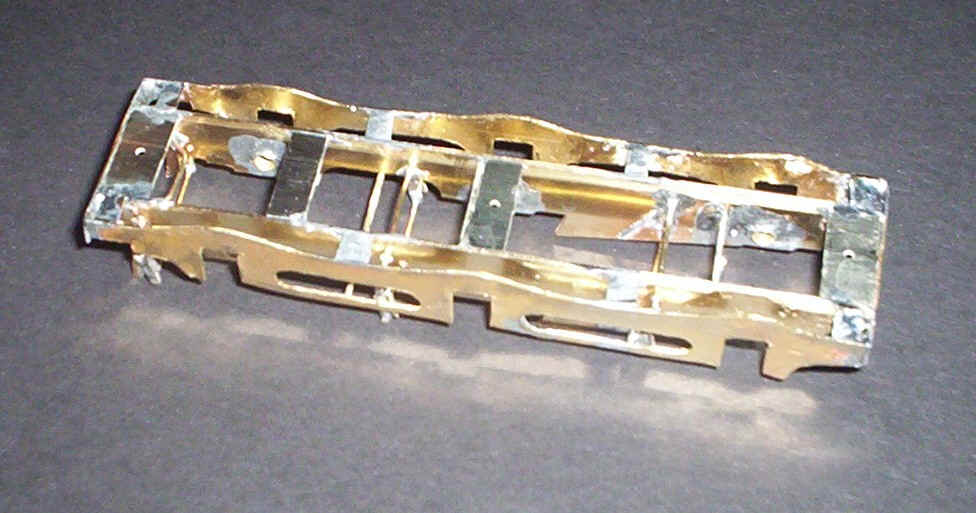
At this stage the frames were a little "curvy" but a few strokes of the file on the front and rear soon straightened them out. The result can be seen in the photo. I plan to add rivet detail etc. later on when I see how much clearance I've got on the running chassis. This will probably be in a mixture of metal and plastic.
The next stage was to build a rigid chassis using the side frames from an Alan Gibson MR 3F. I use 4mm chassis alignment jigs from Comet Models with some extra washer spacers to allow for the width of the S Scale chassis .
Construction followed the usual method of inserting and soldering the bearings, bolting the side frames together using the chassis alignment jigs, and then soldering the frame spacers in place. I used two with holes at the end and three others in various places, both horizontally and vertically. Next the brake shows were fitted and the various cross wires and pull rods that are needed.
For some time I've been pondering how to fit the outside frames and have decided to fit them permanently to the main frames. This goes against normal practice but as the loco is to be free-running I can see no reason why this isn't a practical method (time will tell!). After measuring carefully I decided to fit the outside frames 5mm away from the main frames to allow space for the wheels to moving back and forth on curves.
The first task was to shorten the ends of the 3F chassis to match those of the outside frames. I then soldered a strip of brass 30mm long across the ends of the chassis allowing an equal overlap on each side. The outside frames were then tack soldered to these strips ensuring that the level sections of the frame top were exactly level with the top of the main chassis. Various short lengths of brass strip were used to reinforce these corners. Further pieces and sort lengths of wire were inserted between the chassis and the outer frames to ensure that the brass stays both vertical and straight. In hindsight I should probably have made the outer frames from nickel silver but I'm not intending to cut out another set of frames just yet! After a good wash the completed unit was ready for the test fitting of the wheels and cranks.
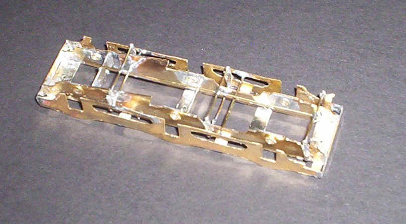
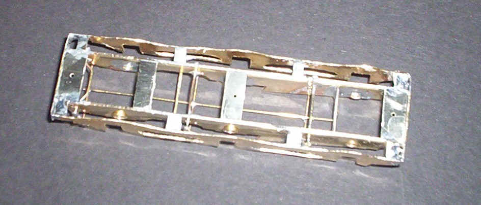
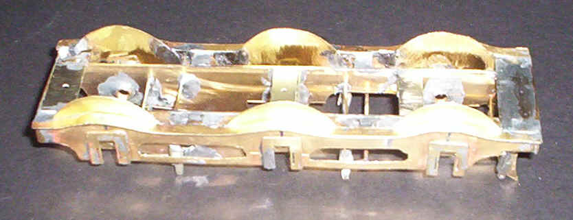
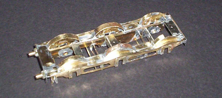
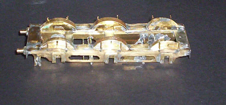
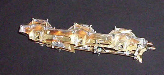
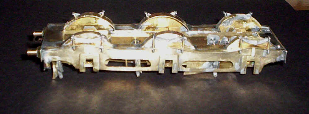
Three views of the completed chassis and outside frames
Experience suggests that it would be a good idea to thin down the front face of the bearings on the centre axle and also to elongate slightly the centre bearing hole to allow for unevenness in track work - in effect this is a crude form of compensation. Having got this far I decided to test fit the wheels and crank pins. Axles 36mm long were cut from steel rod and after pushing the axles through the holes in the wheels to open them up slightly I fitted one wheel by holding it in between the frames and pushing the axle through the hole. After pushing the axle through the second bearing I fitted the opposing wheel and then centred the wheels on the axle at the same time using the back to back gauge to set the wheel positions. Finally I pressed on the plastic cranks to check that they didn't catch on the outside frame. Success at first go: the chassis rolled through all my point work without problems and when tested with a locomotive pushing it caused no short circuits.
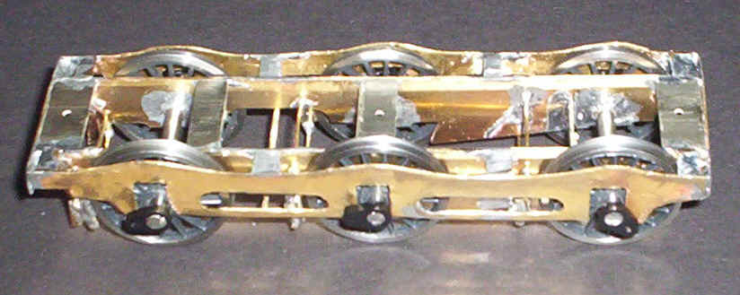
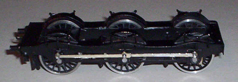
The chassis with wheels and cranks test fitted
After removing the wheels construction continued. I was unhappy with some of the gaps around the axles in the outside frame so decided to solder on some horn block guides from MJT. These U shaped pieces of thin brass are intended to represent some of the pieces of ironwork to be seen on the outside frame. Since my model is intended to be impressionistic instead of "dead accurate" I'm going to forgo the pleasure of putting in all those rivets and have decided that the horn block guides will suffice. Life is too short to do everything that might be desirable. In any case since this is my first real attempt at metal-bashing I'm playing safe. I suppose I could have drilled hundreds of holes and solder in little pieces of wire but for a first attempt I basically want to make it all work.
Two things are now obvious; the axles need to be about 1mm longer at 37mm to allow sufficient side play whilst the footplate will be about 1-2mm too high. I can live with that since all my locos display variations in height of the same magnitude - and they are from kits!
The next step was to solder on the curved running plate on both sides of the outside frame. I found a strip of 3.5mm wide brass from an etching remnant. Amazingly there was enough for both sides. I soldered the strip to the top of the outer frame ensuring that the inner edge was flush with the inner side of the outer frame. Working from one end the strip was formed into that curvaceous profile using a screw-driver blade. A few millimetres at a time was soldered before proceeding until all was secure.
At the front of the chassis I cut another rectangular piece of brass to fill the gap between the two outer running plates and soldered this in place filling the gaps with solder and then filing smooth.
After calculating the height of the wheel splashers, from a diagram in the book, I made a paper template and drew around this onto some thin brass. An extension at the bottom of the splasher was allowed to enable it to be soldered onto the inside of the outer frame. These were then soldered in place and tested to see that the crankpin boss on the wheel didn't catch on the brass.
The chassis showing the horn block guides soldered on the front of the outer frames, the curved running plate and the front of the splashers.
Construction proceeded by fitting a buffer beam together with Alan Gibson brass buffers on double sided paxolin blocks; SMP sleeper strip. Next small rectangles of brass were soldered into the gaps on the running plate between the splashers. These are supported by the brass spacing wires fitted earlier to hold the outer frame rigid (a rare example of forward planning here!). The gaps between the curved footplate and the inserts was filled with solder and smoothed flush. Even after painting there will probably be a mark showing where the two pieces of brass adjoin but I'm sure the running plate on the original was assembled out of small plates.
The splasher tops were now made from strips of brass curved to shape and cut to length by trial an error. They were then soldered onto the tops of the splashers and filed smooth.
I've come to the decision that I'm not going to add any rivet detail to the chassis, nor am I going to attempt the serpentine like strengthening that runs under the running plate. To do so with my lack of skill is likely to result in something that looks messy and draws attention to itself. So, just like my 0-4-4T and its lack of rivet detail on the smoke box I'm going for the impressionistic approach.
The chassis with running plate, buffers and splashers completed.
One of the most obvious features of the Kirtley 0-6-0s was the springs above the running plate. To replicate these seemed, at first, potentially tricky. My plan is to use two pairs of vertical wires passed through the running plate and solder them to the outer face of the frame. Next I'll solder a thin piece of brass sheet to the pair of rear wires and attach some wagon or coach spring castings on to the brass sheet. In reality the spring hangers were attached onto both the front and back of the frame but as I've had to adjust the position of the frames to accommodate the sideways movement of the wheels both hangars are fixed to the front of the frame.
Two holes were drilled through the footplate 7mm from the centre line of the axles and brass wire passed through them. The real locomotive had hangers made from flat metal strips but I felt these would be excessively fragile in model form. The front hanger has a small L shape bent into its end and the two wires are soldered to the front face of the frame. I clipped off the wires at the level of the top of the splashers.
The spring hangers are now soldered in place.
The next step was to cut some "spring shaped" pieces of 0.005" brass and solder these onto the rear spring hangers. Finally a short length of brass wire was solder across the top of each pair of spring hangers. The actual cosmetic springs will be modified S Scale Society white metal castings; the larger ones at the ends will be from MR coach springs whilst the centre ones will be wagon springs. They're obviously not completely accurate but are, without doubt, neater and more consistent than anything I could produce.
The backing plates for the white metal springs are in place.
Cast springs in place.
The springs were fixed with Araldite to the backing plates and short lengths of plastic strip were super glued to the outside frame to represent the linkage to the horn blocks. As mentioned above I've decided against adding any rivet detail to the outside frames as I suspect I'll make a mess of it!
The completed chassis
The Kirtley now has a rolling chassis as can be seen in the photo. After a good cleaning with files, fibre glass pens, toothbrushes and "Jiff " it was sprayed with red oxide primer and then satin black. The coupling rods were assembled next using Alan Gibson's 3F rods with the plain sides both facing outwards. I used the trick of blunting the end of a cocktail stick and using this to hold the pairs of rods together through the holes whilst soldering.
The next stage was to assembled Alan Gibson's plastic cranks and crankpin screws. I took the precaution of smearing a thin coat of Araldite on the back of the cranks so that the pins don't move.
Final assembly was a little nerve racking as I'd got to persuade the axles through two sets of wheels and also ensure that the extended axles were equally centred. I'd already cut some slightly longer axles than originally fitted on the first test runs. First I pressed one wheel onto the axle allowing about a millimetre to protrude at the back of the wheel. This was then located between the two frames and the axle gently pushed through the opposite bearing hole. The second wheel was then very carefully pushed onto the axle using a thin flat file pressing down onto the axle hole. Once this wheel was on I turned the chassis over and pressed the axle right through the wheel, simultaneously gauging the wheels with the SSMRS back to back gauge.
Once I'd satisfied myself that there was an equal overlap of the axle on each side I repeated the process for the other two wheels. The outside cranks were gently pressed onto a spare axle to open the holes up slightly. I then pressed them onto the extended axles positioning them approximately at 90 degrees to each other. A quick test on the layout confirmed there were no problems negotiating the track.
The coupling rods were fitted next with small brass washers between the plastic cranks and the rods to allow a little more flexibility, and also in case the rods should catch on the cranks. The crankpin locknuts were screwed on - I don't fit Alan's bushes as I find my chassis run better with lots of slop in the holes. After a little adjustment of one of the cranks the chassis ran smoothly. Inevitably on of the nuts came off on the layout and I had to search for it in the ballast! Holding my breath I soldered the nuts to the crankpin and gently filed the ends flat.
So that's it a rolling chassis which just awaits pickup wires and, of course, the boiler and cab. The chassis is full of mistakes and is seriously under-detailed but on the layout I doubt I'll notice the absence of rivet heads or the slight discrepancies caused by the need to modify certain dimensions to accommodate 3 feet radius curves. I suspect the buffer height is about 1mm too high but all my locomotives display variations.
The boiler and firebox from copper tube
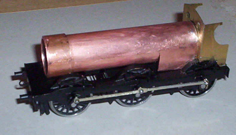
Much thought has gone into the problem of how to build the boiler with its round top firebox. Original thoughts centred around using some plastic plumbing pipe which I'd used for my 0-4-4T. However, on the 0-4-4T the lower part of the firebox isn't visible whilst it obviously is on the Kirtley. Some horrendously difficult ideas occurred but none seemed likely to produce a completely smooth boiler to firebox transition. In the end I pulled out a length of copper central heating pipe which the fitter installing our new system had left with the words, "Some people use these for model engine boilers."
My method for producing the boiler was extremely simple and took less than a quarter of an hour. To ensure a perfectly square end I wrapped a self adhesive address label around the tube and cut to the edge with a small hacksaw. After removing the label I marked the position for the front of the firebox in a few places around the tube and stuck another label with its edge against these marks. I measured the circumference of the pipe using a piece of paper wrapped around it tightly and using this distance marked the two points directly opposite each other on the circumference to show how far I needed to cut the pipe. Once this cut had been made I marked the longitudinal midpoint of the cut line. A cut was then made lengthwise down the tube.
A pair of bull nose pliers was used to gently open out the two flaps of copper to produce the outside of the firebox. Initial impressions suggest that I won't have to cut any more metal as the firebox sides fitted snugly between the rear splashers and the top of the inside frames. A word of warning; remove the labels immediately as otherwise the adhesive is difficult to remove from the metal.
The cab carcass
Next on the agenda was construction of the basic cab structure. The plans from the NRM book were resized on the photocopier and stuck on to a sheet of brass. The curved cut out was made using a piercing saw to create the approximate shape and then the metal was filed to the line on the drawing with needle files. The straight lines were, I'm afraid cut with nothing more sophisticated than my trusty scissors! The front of the cab had two small holes drilled for the windows and then these were opened out with a tapered broach. The base of the cab was cut to fit snugly between the various pieces of metal at the rear of the chassis. The somewhat crude curves at the bottom of the cab sides and front are cut to clear the wheels. The whole lot was tack soldered and once I was satisfied all was square permanently soldered together. The small hole in the middle of the cab front is to allow the boiler to be bolted to the cab.
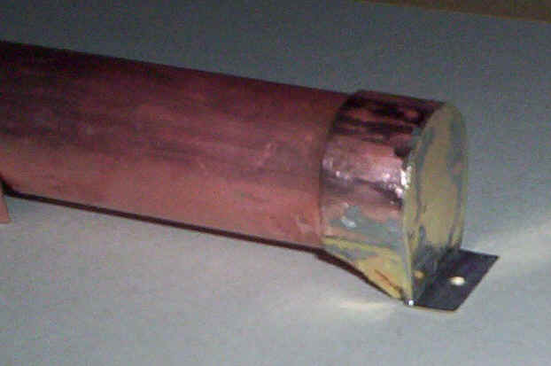
Boiler with end plate complete with bolt hole
Some advice I received from S Scale Society member, Scott Willis, was very timely as he warned of the difficulty of soldering to copper tubes. As it happens I'm a believer in fixing chimneys, domes etc. to boilers using epoxy resin. However, I do need to solder some parts to the boiler the first being at the firebox end of the boiler. My predictions that I wouldn't have to cut any of the metal at the base of the firebox sides were incorrect; in actual fact about 2mm had to be taken off. The end of the firebox was tinned using my large soldering iron - sorry I've no idea what the wattage is but I hate using it! A piece of brass sheet was soldered to the end , cut to shape roughly and then filed flush with the copper tube.
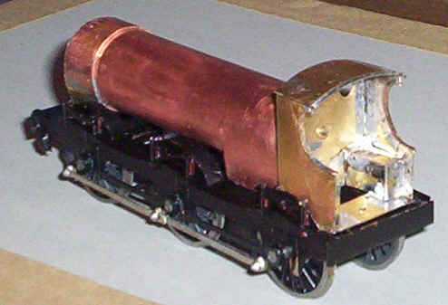
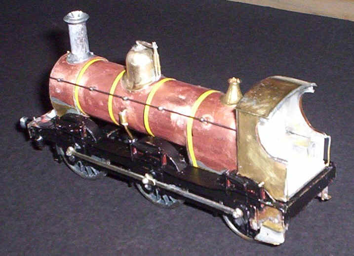
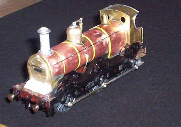
Boiler and cab assembly
The two assemblies were dropped in place on the chassis being held firmly in place by the rear and front splashers. A hole was now drilled through the cab front and the rear of the boiler and the two parts bolted together. A quick check showed that, for once the boiler was dead level and at the correct height. At last it's beginning to look like an engine as the photo below shows
The first sight of a locomotive!
Attention now turned to the smokebox. First of all I inserted a slug of lead into the boiler and secured it with epoxy resin. After tinning both the main boiler tube and the shorter length for the smoke box wrapper a piece of brass sheet was soldered on to the front of the boiler. It was trimmed roughly and then dressed with a file to match the profile of the smoke box. At the base the brass was filed to the curved profile of the smoke box saddle. At the base of the smoke box I now solder on some small pieces of thin brass curved to match the profile of the front of the saddle. The joint between the brass and the smoke boxes was flooded with solder and filed to give an almost unnoticeable joint. Most of this will lie behind the splasher tops anyway. Some minor filing of the splasher tops was needed before the boiler sat at the required height.
Thoughts now turned to how I was going to secure the boiler and cab to the chassis. In front of the smoke box I solder a strip of brass with a hole drilled through it and the frame spacer at the front of the chassis. A bolt will be concealed eventually underneath the decorative plates in front of the boiler. Similarly a hole was drilled through the cab floor and rear frame spacer. Eventually the entire boiler and cab unit will be fixed semi-permanently to the chassis with these bolts.
The arrangements at the front of the smokebox.
The next task was to complete the cab. Some phosphor bronze strip was soldered around the cab openings and trimmed to length. A piece of 0.15 brass was cut for the roof and soldered in place. A length of brass wire formed the strengthening bar apparent in photographs and was soldered on the rear edge of the cab roof. Finally the boxes that cover the rear driving wheels were assempbled from some 0.10 brass cut, scored, bent and soldered in place. The cab was bolted to the boiler/ firebox unit and checked to ensure there were no short circuits. Attention now moves on to the detailing of the boiler.
Cab roof and wheel covers fitted
Now for a confession. I completely forgot to fit the cab steps when I was building the chassis! Rectifying this omission was a little fraught. First of all I soldered a piece of 0.09 brass wire into the corner of the outer frame and the rear drag bar. Then a piece of brass was cut to fit the space where the step back plate was on the engine. Some paint was cleared off the frame and the curved rear section tinned. The brass was then soldered to the wire and a butt soldered joint made with the frame. Some steps were fabricated from thin brass by scoring with a knife and bending. The lower step is a lot longer than the upper one.
Once this was accomplished it was out with the drill to make the necessary holes in the boiler. The chimney is an S Scale Society casting intended for the Y7. It's too narrow as it comes but I simply super glued a paper wrapper around it and then flooded the paper with more glue. This seems to give the required diameter. The joint was positioned at the rear of the chimney to make it less obvious although I'll probably rub over it with a piece of wet and dry paper.
The dome is an Alan Gibson lost wax casting and had to have the horrendous sprue cut from underneath it. A small washer was soldered to the pip at the top of the dome and then a pair of Alan's lost brass Salter safety valves were soldered to the washer and also to the lip of the dome at its base.
The clack valves on the side of the boiler and the associated pipe work are built as one assembly linked under the boiler. A length of brass wire was bent to a rough U shape and two short lengths of brass tube were soldered in place to represent whatever that piece of equipment does in real life.
I decided it was time to join the cab and boiler at this stage so bolted them together, checked that the holes for the securing bolts at the front and in the cab lined up with the holes in the chassis spacers and then soldered the lot together. To my amazement the whole lot actually fits without any hideous gaps around the splashers. The boiler and cab unit can still be separated from the chassis at the moment but will have to be semi-permamently fixed once couplings are in place.
The chimney, clack pipework, dome and spoke box door (another Alan Gibson brass part) were fixed with Araldite after making sure everything was vertical and central.
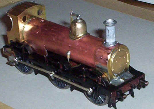
The picture shows the cab footsteps and some of the boiler furniture fitted.
Construction was now at that stage where it's basically just adding details to, hopefully make the locomotive come to life.
So in roughly this order the following things were done:
A strengthening piece of 0.9 wire was soldered under the cab roof.
The front of the firebox was made up out of a piece of 20thou black plastic pushed up into the slot made when the boiler was cut to make the firebox. As usual it was secured with epoxy adhesive.
The rear of the firebox was cut out of plasticard and fixed to the inside of the cab.
A cab floor, also of plastic, was fitted.
The curved "piano" in front of the smoke box door was made up of the three layers of plastic glued to the front fixing plate. this was then filed to shape and covered cartridge paper "superglued" to the plastic. The paper was then soaked in more adhesive to make it hard.
Holes were drilled in the smoke box door for the handrail knobs and also into the cab front for the handrail wire.
The body was now thoroughly cleaned with a fibre glass pen and washed with "Jif" to remove all traces of grease etc.
Narrow strips of self adhesive PVA tape were cut and fixed to the boiler in the appropriate place.
Handrail knobs from a redundant Airfix "Royal Scot were super glued into the holes and the handrails fixed in place on the boiler and smoke box door.
A small piece of card for the locomotive number plate was fixed to the smoke box door.
The buffer heads were inserted and fixed with epoxy.
The locomotive ready for the paintshop.
The tender
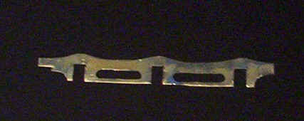
So having largely finished the locomotive it was time to start on the tender. Once again the diagrams in the NRM book were re-sized on the photocopier. The first piece of metal to be cut was the tender footplate out of 0.01" brass. This had a rather awkward shape cut out in the middle, as can be seen in the photograph. The small pieces that protrude into the main opening are the motor unit fixing points. These will later have holes drilled in them for the self tapping screws that will hold the tender drive unit in place. The hole was cut out by first drilling holes at every corner followed by using a piercing saw to cut the brass; there was no need to be particularly careful about this so the cuts are anything but straight!
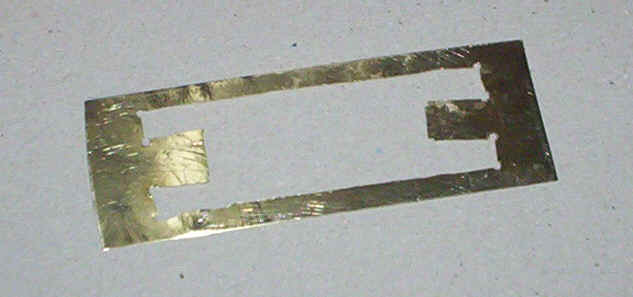
The tender footplate
The tender frames were cut next. as I've now bought a piercing saw I used this to open out the oval holes. I snapped a blade doing this but for a beginner using these very fine blades I don't think that's too bad!
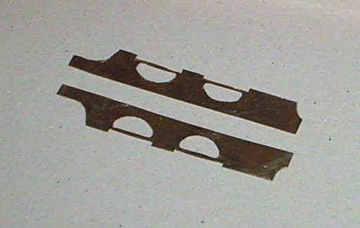
The tender frame sides
A rear buffer beam and front drag bar were cut from sheet brass. Assembly of the tender started with the soldering of the rear buffer beam to the footplate, followed by both side frames and then the front drag bar. The tender drive unit (see the page about converting the Airfix Royal Scot tender drive to S Scale) was offered up to this assembly and the positions for the screw holes marked, remembering that these are off centre because of the gear wheels on the back of the plastic Airfix wheels. The holes were drilled and opened up with a broach. Two short lengths of brass tube were cut to size as spacers for the self tapping screws that come with the Airfix unit. The screws were tightened and the brass tubes were soldered in place very quickly to avoid damaging the plastic.
To my delight the height of the tender footplate exactly matches that of the locomotive so no adjustment was necessary. The fine nickel silver wire I had originally fitted as pick up wipers has been replaced with brass as I find that sometimes the wires loose contact with the wheel treads. A quick test proves that there don't appear to be any short circuit problems and that the tender will run smoothly.
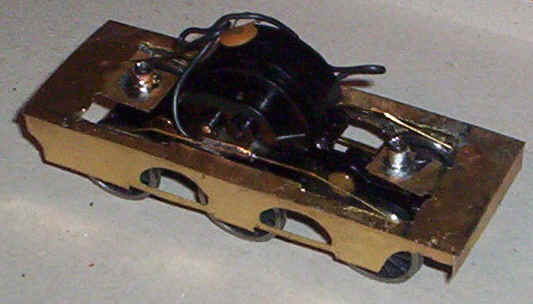
The basic tender under frame is complete
The next stage was to build the tender tank, again using 0.01" brass. To form the flare at the top of the sides I simply placed the edge of the sheet in a vice and gently bent it in stages until satisfied that the curve was correct. The rear of the tender tank was soldered in place first - the broad platform at the rear of the footplate is a most unusual and distinctive feature of the Kirtley 2000 gallon tenders. The sides were added one at a time ensuring that they made a neat joint with the rear. Once satisfied with the position of the sides I flooded the joints with solder.
At the front of the tender there was a somewhat strange open space for coal, almost like a bath tub which it isn't really possible to replicate with a powered tender. I decided to add a cross strengthening piece just in front of the leading wheels and disguise this discrepancy with a generous load of coal.
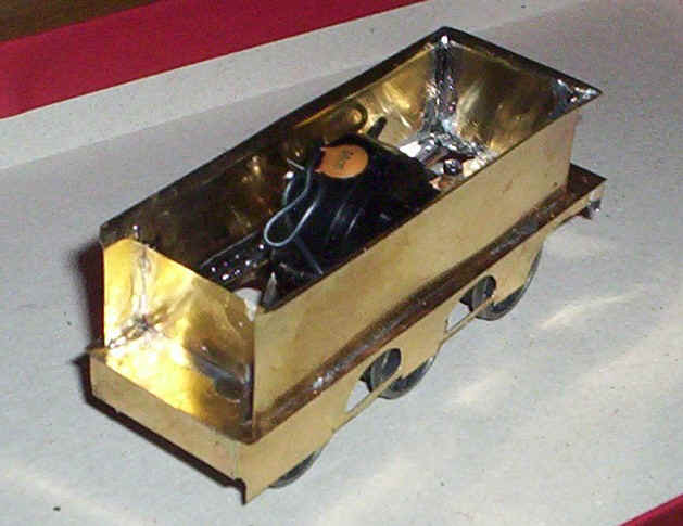
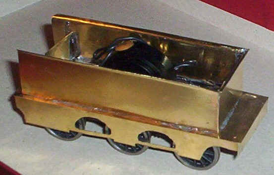
The tender body is basically complete.
One of the problems that I'd been concerned about was how to build the removable tender top. The design of the Kirtley tenders was very different to the Johnson and Deeley tenders that I'd built so far. The coal was contained in a bathtub shaped recess surrounded by extension to the main water tank. In the end I succeeded in making the tender top which is removable and gives an impression of this curious arrangement.
The first step was to remove part of the brass cross piece at the front of the tender body. Two vertical saw cuts and some brutal bending backwards and forwards of the metal saw the centre part snapped off. Some thick plasticard, about 40thou was glued inside the tender sides to form the support for the tender top.
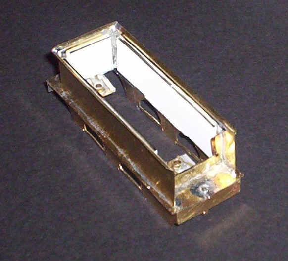
The tender with the supports for the top
The removeable tender top was made in much the same way as for my other locomotives. A piece of 30thou plasticard was cut to fill most of the tender . A hole was cut in the centre to allow the top of the Airfix tender drive unit to protrude slightly. Pieces of plastic were then added around and then over the hole to cover the opening. At the front end I cut a recess about 15mm long and about 20mm wide to give the impression of the coal space. A sloping piece of plastic was then glued in place. This will eventually be covered in coal and will hopefully give the impression of a locomotive that has just been coaled. Numeroud small pieces of plasticard were cut to complete the front end as can be seen in the photograph. The black outlines should give an idea of what I did.
Tender top in place
Completion and detailing of the tender followed my usual steps:
Tender footsteps were added and the buffers soldered onto paxolin spaces as on the locomotive.
Lamp brackets were from brass wire soldered into holes drilled in the rear running plate.
Handrails and the prominent tender hand brake were soldered in place.
A coupling bar to link the locomotive and tender was made from a strip of brass.
Plenty of lead was packed inside the removable tender top. In addition to compensate for the smaller space available within the Kirtley tank I also filled the space behind the buffer beam and under the footplate at the front of the tender frame with lead.
For the tender springs I used the springs from Alan Gibson's MR tender spring and axlebox castings. In retrospect perhaps I should also have used these on the locomotive as they are a little "beefier" than the coach springs I used there.
The axle boxes and horns were made from various pieces of microstrip and plasticard superglued to the brass.
A Bachmann coupling was secured to a block of plastic.
Alan Gibson castings for the two toolboxes were fastened to the tender top and a water filler made from blocks of plastic card.
I coated the tender top with a layer of epoxy resin and then sprinkled on a load of coal. This will be built up further in due course.
The final constructional photos of the tender
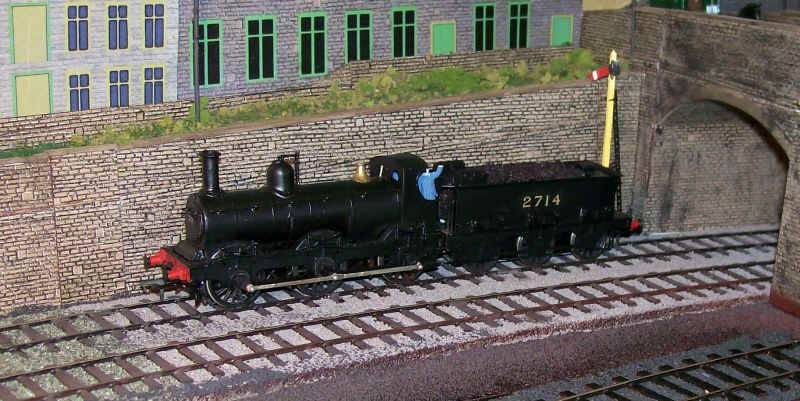
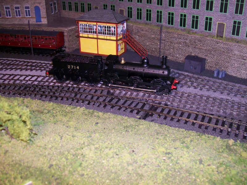
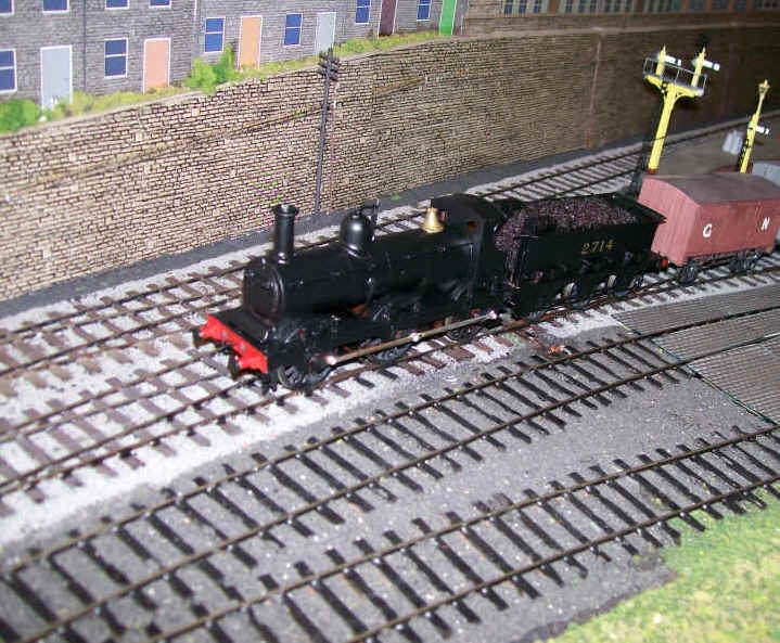
The final stages of construction being over the locomotive was broken into its various parts and cleaned ready for painting. Not surprisingly the chassis needed some remedial work on the paint already applied. The bare metal was primed and then the whole chassis repainted by hand using a mixture of matt and gloss black to give a slightly satin finish. The tender and loco bodies were sprayed in satin black and left to dry for 24 hours. The buffer beams were painted red and the locomotive finally assembled. To my delight the locomotive runs beautifully smoothly, although it's not quite as powerful as the other locomotives; there's considerable less room for lead in the body and even though I've crammed lead into various other places it is still somewhat lighter than I'd prefer. Nevertheless it still pulls 14 wagons, which is more than the present layout can actually accommodate in one train.
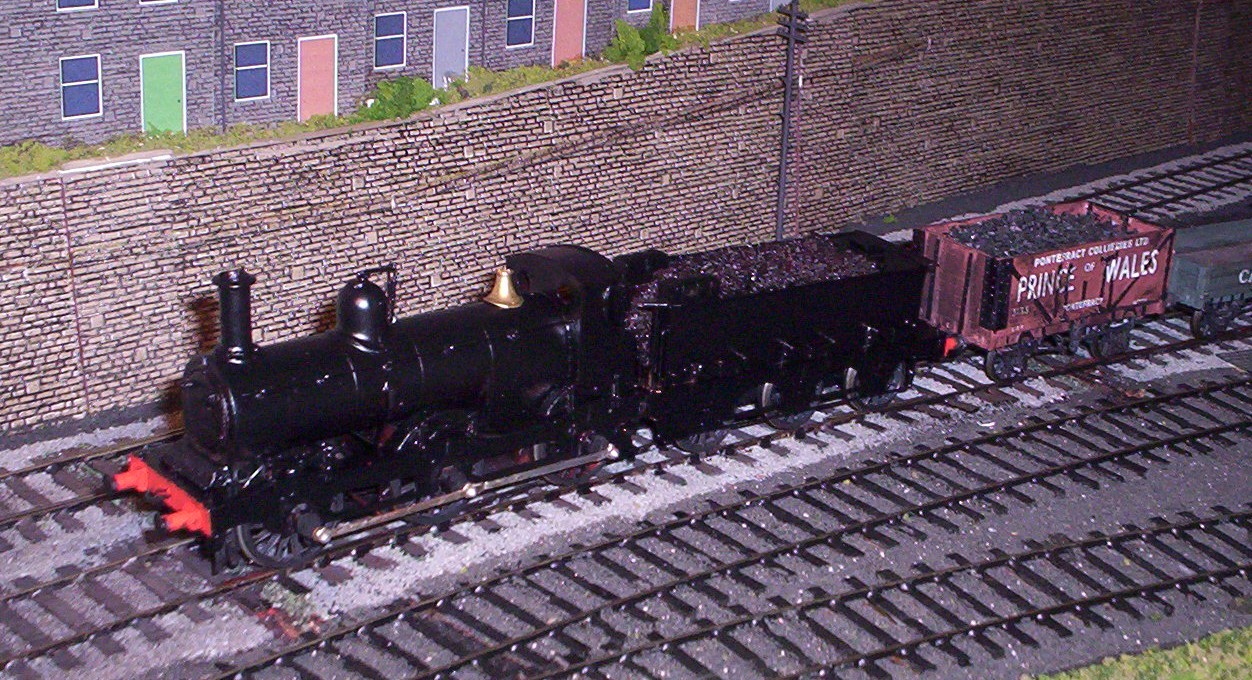
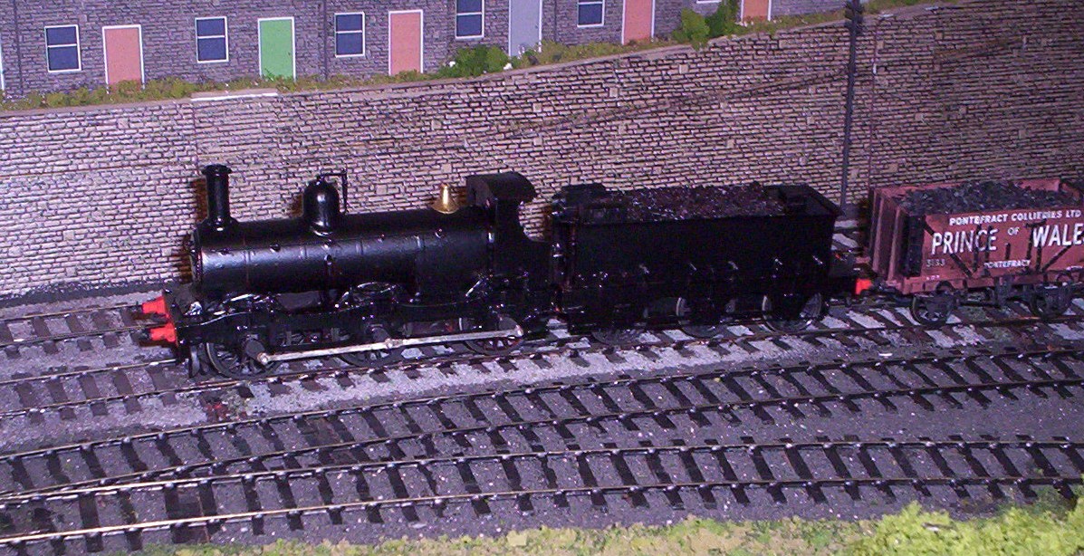
The locomotive awaits numbering, a crew and a better load of coal