Modifying a Alan Gibson Johnson 2F 0-6-0
Having been alerted by other members of the SSMRS I discovered several items on Ebay which looked attractive enough for me to bid for, and win!
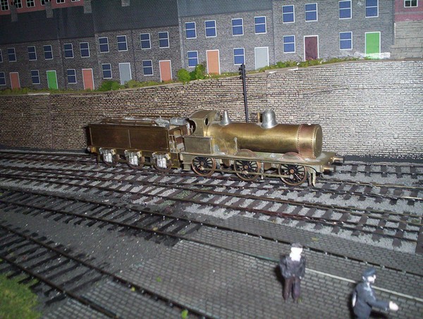
This partly built model is clearly an Alan Gibson kit Midland 2F loco, with the standard Johnson 3250 gallon tender. By the time I started modelling in S Scale Alan had discontinued this kit and I'd expected to have had to scratch build the locomotive body myself. Needless to say I'm rather pleased to have picked this model up.
I'm going to have to modify the model since it's not powered. The wheels have shorting out strips on opposite sides of the loco and tender chassis, which is something I don't like. I prefer to have pickup off all wheels with the body electrically dead. As it stands the wheels in locomotive chassis are very stiff and would have to be removed anyway. I don't think there's enough side play to cope with my sharp curves. Strangely the coupling rods are not jointed
I'll convert the tender to my usual tender drive system and replace the loco wheels with EM Gauge profile ones, which I've already got in stock. Not immediately apparent, is that the splashers and sandboxes on the other side of the loco are missing so these will need fabricating.
I'm not too convinced by the cast metal safety valve cover. I think I prefer the brass ones I've fitted to all my other Johnson locomotives.
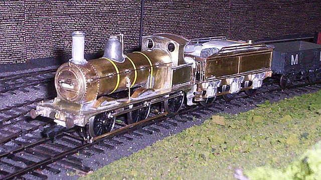
Here's the largely completed model. The modifications made to the model were:
Locomotive
Rebuilt chassis with 4' 3" drivers.
Sandboxes removed as in the series of locos the model is to represent there weren't any in the position already on the chassis.
Outside brake gear from 1mm square brass section.
New splashers fabricated for the left side of the locomotive.
Cast safety valve cover removed.
Injector pipes fitted on both sides of the boiler.
Reversing lever fitted.
Smoke box door, lamp irons, handrails and chimney added.
A fall plate was soldered to the cab floor to cover the gap between loco and tender.
A loop of wire was soldered to the loco drag beam to act as a coupling between loco and tender.
Boiler lagging strips are from self adhesive car "lining tape"
The curved "piano front" is a curved piece of brass secured between the boiler saddle extensions with epoxy.
The model had been built with the buffers soldered directly onto the VERY thick buffer beam. I've decided against removing them and soldering onto raised pads as I suspect that they won't come loose easily.
Tender
The original tender has been put into store and a completely new tender assembled from a modified Johnson 3250 gallon kit to produce the correct smaller 2300 gallon version.
The tank sides, front and rear have all been reduced in height by approximately 2mm. This was done by scoring with a heavy duty craft knife and then snapping the waste off. To restore the lower beading I soldered 1mm wide brass strip along the bottom edge of the tank sides and rear. The bottom of the central vertical beading was filed away to allow the strip to be continuous across the sides.
The tender was then assembled as described elsewhere on this site with my usual tender drive unit.
The removable tender top has to be slightly different to accommodate the top of the motor which protrudes about 2mm more on this tender than for the other Johnson tenders due to the lower height.
The toolboxes were mounted on the removable top supported on triangular pieces of plasticard.
A U shaped piece of brass was soldered to the tender drag beam as a coupling.
The locomotive and tender are not permanently coupled and pick up is only off the four tender wheels - these seems sufficent for good pick up.
By way of a change a black and white photo of the finished model, just as it would have been photographed back in 1922.