SCRATCH-BUILDING A M.R. 0-4-4T
For Halifax Midland I built a M.R. 0-4-4T to pull the local trains. As the layout developed I realised that a second loco of the same type would make operation a lot easier especially when changing locos in the fiddle yard. 0-4-4 tank locos are not easy to re-rail! The first 0-4-4T was built in 2003 - 21 years later I finally got around to starting construction on the second loco.
Fortunately, I had bought a second pair of frames and loco wheels together with chimney, dome and safety valve cover from Alan Gibson all those years ago so in 2024 I was able to start construction on the second loco. There will be several differences between the two models.
The first description below is of the original model whilst at the end I will detail construction of version two.
The first 0-4-4T built in 2003
The completed model
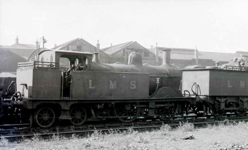 |
Photo of 1252 at Derby ; photo by G.E.Rabone
Click on the photos to see larger image
Inevitably I was going to have to do this one day; scratch-build a locomotive. Many M.R. locomotives are available in S Scale courtesy of Alan Gibson, but one I particularly wanted is the Johnson 0-4-4T to pull a set of suburban coaches. Now, 0-4-4Ts have an evil reputation among modellers but Alan came to the rescue. He'd already produced a set of frames for this type for somebody else and in due course they arrived. In truth I'm not really having to scratch build the loco chassis, as virtually everything used in it is sourced from other kits or components. On the other hand I'm having to make decisions which up to now have been made by the kit manufacturer - experience gained over the years is now being put to use!
Alan's advice about how to build one as a rigid framed locomotive has proved invaluable. My track-building standards aren't particularly good so I ordered a set of Alan's 5'3" wheels with EM gauge profiles and I decided to use some 4mm Jackson wheels for the pony truck with their slightly more forgiving wheel profiles.
I demolished one of my redundant 4mm scale locomotives to give me a Portescap motor with gearbox, and the same loco yielded an ex-Comet 4 wheel bogie, which had exactly the correct wheelbase for the 0-4-4T's bogie. Although it's too narrow I'm using this to my advantage by allow quite a lot of side play on the axles.
I started construction by opening up the 1/16th holes that were in the frames using a reamer to allow standard 1/8" top hat bearings to be inserted, which were duly soldered in place. Alan suggested I vertically elongate the rear driving bearing to give a little compensation. Frame spacers came from some spares from one of Alan's other kits. A drawing from Essery and Jenkinson's "An Illustrated Review of Midland Locomotives" was rescaled on my photocopier and I was thus able to work out where to put the spacers with holes to fix the footplate and body - under the smoke box and the coal bunker.
In setting up the chassis I used the OO Scale frame spacer jigs from Comet, packed out with washers to give the correct S Scale width. Once I was satisfied that the frames were aligned correctly, I soldered in four frame spacers. The spacer directly over the bogie also had a pivot hole drilled through it. After cleaning up everything I assembled the wheels on the bogie with four washers between the wheels and the much narrower 4mm scale bogie. This extra side play will give considerable flexibility on my sharp curves - in fact without it the loco won't be able to traverse the curves given its rigid centre pivot. Alan suggested I simply place washers between the bogie and the bogie pivot plate until the frames sat level.
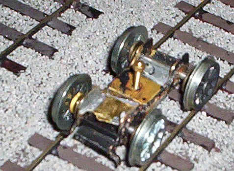
The 4mm Comet bogie used for S Scale. The wheelbase is spot on for the 04-4-T. Only one washer was placed between each wheel and the bogie.
I then placed a wheel on an axle and threaded wire through the pre-drilled holes in the frames for the brake hangers. Some more spares from Alan Gibson kits provided four brake block hangers. The cross wires at the bottom of the hangers were added next to give rigidity. I prefer to have the pick-up wires under the chassis where I can adjust them easily, so I soldered some copper clad sleeper strip to these cross wires. Once painted black they become almost invisible when the loco is on the track. The copper is gapped so that the section between the cross wires is isolated from the chassis, otherwise there's a short circuit when the loco is wired up!
At this stage I track tested the chassis to see if it ran on the layout, which to my amazement it did perfectly. The only adjustment needed was some filing away of the brass over the bogie wheels to eliminate the occasional short circuit when the bogie wheel touched the chassis. The final task was to solder in the wheel guards at the ends of the chassis. These were simply brass strip cut to shape.
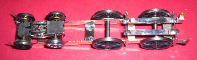
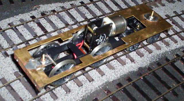
The chassis from below showing the copper clad sleepers strip to mount the pick up wires
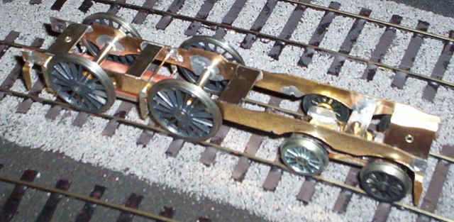
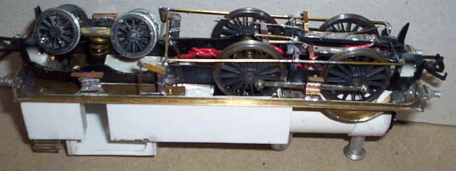
The chassis from above showing the simple pivot for the bogie
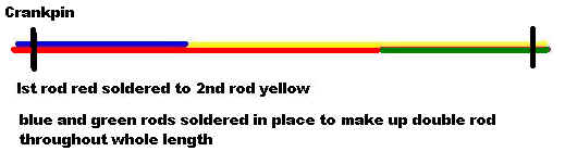
The next task was to fabricate the coupling rods. Fortunately the 0-4-4Ts had plain rods, so I was able to make some using some spare 4mm LMS Class 5 rods. I put London Road alignment jigs into the bearings and soldered up the rods. Basically I first took the front left hand rod of the Class 5 and overlapped it with the rear right hand side rod joining them so that the jigs held them in the correct spacing whilst I soldered them together. I then cut further sections of the Class 5 rods and built up a double rod throughout the entire length. Any gaps were filled with solder and then the whole thing was filed until it looked as though it was a continuous rod.
The diagram should help clarify this. I could, of course, have fabricated rods myself but the task was made so much easier adapting existing components.
Once these were made and the chassis had been sprayed black, it was time to assemble everything. The rear driving wheels were fitted first together with the Portescap motor and several washers as spacers between the frames. Alignment of the wheels was done by eye, the holes in the rods were opened up with a drill and reamer and they were then slipped over the crankpins. I didn't use the bushes that Alan supplies with the crankpins. To my surprise the chassis rolled without any hint of binding, so power was applied to the motor with a smooth turning of the wheels first time!
The bogie was fitted with about five washers to obtain the correct height. Nickel silver pick up wires were soldered to the copper clad strips and the motor wires connected. Some lumps of lead were laid on the chassis and away went my 0-4-4T happily around my layout. It comfortable propelled three carriages and about ten wagons. Now all I've got to do is build the body!!!
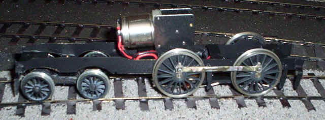
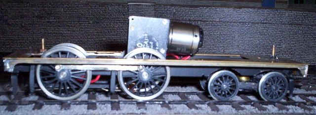
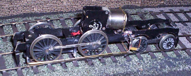
The completed and running chassis
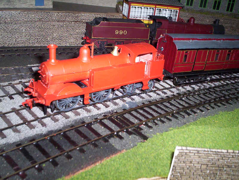
Having got the chassis running, I decided the next steep was to build the footplate. Once again my box of bits came in very useful. I had an Alan Gibson M.R. 990 class kit which I'd originally bought fairly cheaply, with the intention of rebuilding to a Compound. Clearly the straight footplate of the 990 wasn't going to be any use for a Compound so I thought why not use it for the 0-4-4T if it would be suitable. It was!
All that was necessary was to shorten what was the front end by about 10mm, and turn the entire footplate back to front. The 990 splasher holes are almost in the right place. The one for the rear driving axle needed extending about 8mm forwards ( easily modified with a pair of scissors!) whilst the front splasher hole will need filling with a spare piece of brass at the front. The footplate valancing was shortened slightly before soldering and the curved ends modified to more resemble those on the tank. The final task was to solder on an extension piece for the front securing nut and to drill holes front and rear for the bolts.
This locomotive is turning out to be more an adaptation of other kits than scratch built! Running trials with lots of weight added to both the front and rear of the chassis suggest that I've got a nice smooth running and powerful piece of motive power. Now for the body proper..............
Having progressed this far, I initially decided to build the rest of the locomotive completely from metal. A friendly central heating engineer had left me some copper and plastic piping. Amazingly, they were exactly the size I needed - roughly 22mm in diameter. I cut some of the copper tubing to the correct size with a slot to accommodate the motor and also produced the front of the cab from sheet brass. These were then soldered together and tacked to the footplate. It was then that I realised I really didn't want to build the body in metal after all. It's one thing to solder together an etched brass kit where the parts have been designed to fit, and another to measure and cut out metal. put simply I really didn't want to do it. So, it was back to the plastic!
However, I decided that the splashers had better be brass as they are definitely part of the footplate. A photocopy of the splashers was stuck on to brass, soldered in place and the splasher tops were cut, bent and soldered in place. Next I decided, that as I was going to build the loco body onto a plastic base plate, I'd better think of a way of securing this absolutely firmly to the footplate. Araldite on its own wouldn't be secure enough. What I did was to drill a series of six holes at the front, rear and centre of the footplate through which small bolts would lock the plastic body to the footplate. In addition I added a cross piece of brass, just in front of the motor, to give a secure fastening near the front of the water tanks.
The buffers on the M.R. 0-4-4T were mounted on very heavy mounting blocks (I don't know the technical term) which were a distinctive feature of the class. I found some white metal buffers LMS coach buffers with blackened steel heads in my parts box. They're aren't quite correct, but are close enough. For the mounting blocks I used 4mm copper clad point sleeper strip. Holes were drilled in this to accept the shank of the buffer body and the strip was then cut to the size of the buffer base. This was soldered in place on the buffer beam and the buffer body was then soldered in place on the strip. A good clean up and it's time to start on the plastic construction.
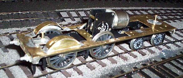
The footplate with splashers, securing holes and buffers in place.
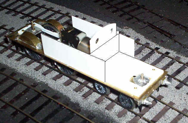
The next task was to make and attach the plastic "base" which will act as the foundation for the side tanks, cab and coal bunker as well as for the smoke box saddle. I used the thickest plasticard I'd got, 60thou I think. I cut out two pieces, one for the front of the footplate onto which the smoke box saddle and frame extensions will be attached, whilst the second larger section at the rear will support the side tanks, cab and bunker. Allowance was obviously made, along all sides, for the thickness of the plasticard I'd be using, as well as the narrow ledge along the footplate between the sides of the tanks and bunker and its edge. To ease cutting and reduce distortion I drilled small holes in the corner of the holes that needed to be cut out. The plastic was roughened on the underside and Araldite smeared thinly over the plastic. After the adhesive had set I drilled through the holes in the footplate and secured the plastic firmly with small 12BA bolts and nuts. The photo shows the bolts before shortening. Finally a further strip of 60 thou plasticard was cemented across the "foundations" just ahead of the motor to join the two sections of plastic more firmly.
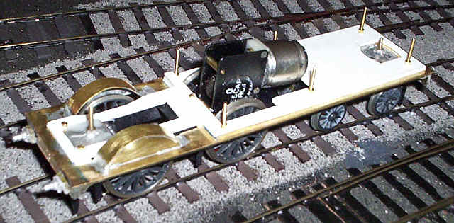
The body "foundations" with the small bolts I've used to make sure that the body doesn't separate at some time in the future from the footplate. At the front are two bolts secured underneath the footplate whilst just in front of the motor another bolt secures it to the cross piece of brass I'd added. The remaining six bolts will be shortened before preceding.
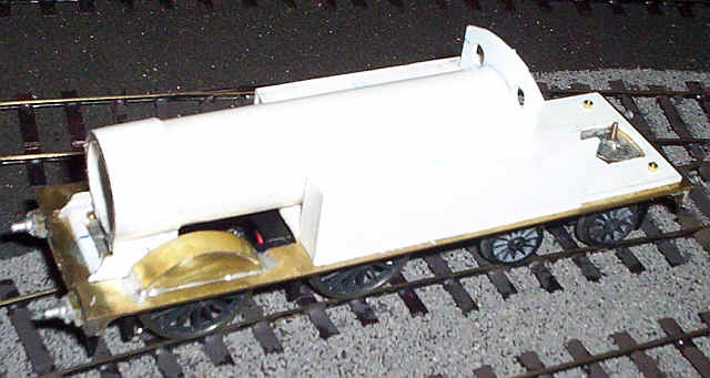
Construction of the body proper now started with the two side tank outer sides being cemented to the base. A cross piece joined these together at right angles on the inside of the "cab2. Onto the front of this I cemented the front of the cab - the two windows having being opened out with a reamer. On the photo I've drawn lines to show the edges of the plastic as obviously white plastic doesn't show up very well. All plastic used in this stage was 40thou.
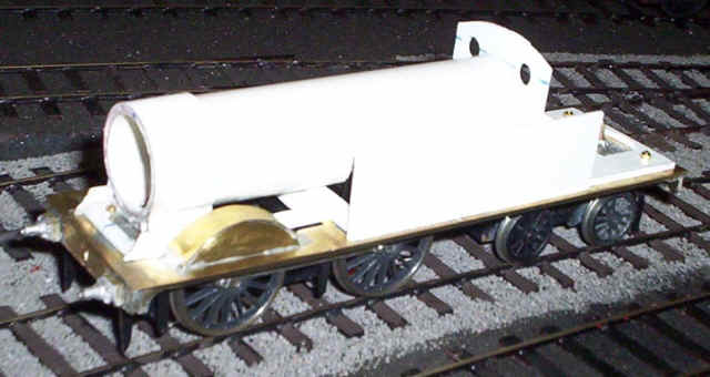
The next step was to install the boiler. Firstly, a length of plastic tube about 21.5mm diameter was cut to length and a slot cut for the motor. A hole was cut in the base of the tube, where the smoke box will be, to allow the chassis securing bolt to pass through. I then took a strip of 30 thou plasticard cut to the correct width for the smoke box wrapper and wrapped it round a pencil to over bend it. This was then secured around the boiler using Plastic Weld. The smoke box was then placed overnight in a lightly tightened vice to allow the adhesive to set firmly. Next day I cut a semi circle of 60 thou plasticard to the inner diameter of the boiler and secured this to the correct position on the front of the cab.
Meanwhile, two strips of 40 thou plastic were laid across the "foundations"; one just behind the two front bolts and the second just behind the chassis fixing nut. These gave the correct height for the boiler to lie level. The boiler was now secured in place at both the cab end and also on the two strips at the front. To reinforce this joint I added 12mm strips of square micro strip underneath the smoke box.
The smoke box saddle was built up in two parts. Small pieces of 40 thou were cemented on either side of the "foundations" just in front of the splashers. A note here; the splashers are actually slightly too wide because, having used the 990 footplate, the wheel openings are slightly too wide - thus the front face of the splashers are set too far out. As a result the splasher tops have to be extended further back to hide the wheels - it's a slight irritant but one I'm prepared to accept. I doubt it will be so obvious once the model is painted.
The final stage was to cut and shape some 20 thou plasticard to represent where the smoke box curves down inside the saddle. The model is beginning to resemble a locomotive at last!
The next step was to remove the part of the "foundations" that can be seen just behind the splasher. I'd thought that I'd need this to ensure that the smoke box saddle was firmly fixed in place but it's become clear that the adhesive plus the small bolts are sufficient.
The side tanks were now built up using more 40thou plastic. The front ends were added first, followed by the supports for the "floor" of the tanks. Strips of lead were then added inside the tank and finally the top was cut to fit inside the sides and end. Unfortunately, photos of white plastic don't show up very well. finally a slug of lead was added inside the front half of body. Track tests show that traction will be more than sufficient with all this weight
Attention was now turned to the bunker which was built up in a similar way to the water tanks. First I positioned the rear cab wall and then added the sides and rear of the bunker. The water tanks and bunker extend into the cab door area, with the roofed cab being noticeably narrower than the tanks and bunker.
The next item I added was the coal rail assembly. This was drawn out on a piece of card and the hole fabricated from left over strips from some etched nickel silver which were just the correct width. Holes were drilled in the bunker top for the 6 uprights and the assembly fixed in place with Araldite.
Next top be added were the cab sides. To cut this part from plastic looked impossible until I realised I could treat at as a window with round corners. So first I drew out the required opening in a piece of 40 thou and after removing the centre - 2 horizontal and 2 vertical cuts, plus four small diagonal cuts - and then round off the corners with a file. The next step was to cut away the bottom of the "window" and trim the top edge to leave a strip about 1.5mm wide. This fragile piece of plastic was then cemented in place between the front and rear cab ends. Another rectangular piece of plastic was cut to fit snugly between the cab sides and ends, thus reinforcing those fragile eaves.
By now the model was starting to look like a MR 0-4-4T so I felt it was time to add the boiler top furniture. The chimney problem was solved by taking an S Scale Y7 chimney, slicing it into two parts just below the lip, removing about a millimetre from the main body of the chimney, and after filing both parts to fit gluing the two bits together with Araldite. Hopefully, it will stay in one piece.
The dome is an S Scale Alan Gibson casting, which will eventually have Salter valves added to it, whilst the safety valve cover is a 4mm GWR lost wax casting, again from Alan. The chimney and dome have been glued to the boiler but the safety valve awaits fitting after painting, to avoid a tedious clean up job.
The loco's smoke box door is actually taken from a 4mm Airfix 0-6-0 cemented on to a piece of 20 thou and fastened to the front of the boiler.
Below footplate level I now added steps cut from brass and strengthened with some L shaped brackets of brass wire. The chassis has also had the brake pull rods added - the 0-4-4Ts had these outside the wheels as well as various other bits of ironmongery to connect it all to the hand brake and vacuum brakes. I've gone for the representative rather than absolutely fidelity to the prototype.
I now fitted the couplings to allow loaded test running. Blocks of plasticard were Araldited to the body behind the buffer beam and to the rear frame spacer of the chassis. These were then built up to the correct height to accept the NEM plug in coupling box of the Bachmann couplings I use on all my stock.
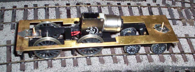
Initial test running showed up two things; the loco needs a little more weight which will be easily dealt with and secondly pick up from just four wheels leads to the occasional stalling on dirty track. Initially I though about adding pick ups to the bogie but a simpler method was to use additional sprung phosphor bronze pick-ups between the two coupled axles. This is a technique favoured by many German N scale modellers, with a firm producing conversion kits for steam locomotives. I simply soldered some short lengths of phosphor bronze to the copper clad strips under the chassis and bent these to pick up from the rail. It's important to make sure that the ends of the strip curve upwards at the end to ensure they don't snag on rails at point work. The photo below shows how these are arranged.
Running was immediately transformed with very slow running achieved. How the strips will survive in traffic remains to be seen, but replacement is a simple task. To my delight, despite the long overhang at the rear coupling to carriages, even on my sharp curves, hasn't been a problem. Neither has the loco any suggestion of "tail end waggling. I suspect this must have something to do with the bogie carrying a substantial part of the locos weight.
As running trials continued I realised that these pickup strips were clearly not made of stern enough material to copy with the continual flexing they experienced and, eventually, I realised that they weren't even touching the rails! Strangely performance continued to be satisfactory. I suspect that this is a case of the running in process and the railheads being cleaner than at the beginning of the trials. Anyway, the upshot was that I've now removed the strips. Nevertheless, I still intend to revisit this area of pickup should running deterioate.
The final finishing of the body was now in sight so I decided to complete adding the various details fairly rapidly. The aim is not to make a super-detailed model so I've limited details to things that I felt were significant when looked at in photographs and that would be relatively simple to add. I've decided not to attempt, for instance, to add any rivet detail, even around the smokebox, as I suspect I'll not achieve consistent results.
Thus in fairly quick order I added
The curved plate under the boiler from brass and glued in place.
The vacuum and carriage heating pipes at front and rear.
Lamp brackets front and rear - brass at the front and plasticard on the bunker.
Dummy coupling hooks.
Handrails to the cab doors and front of the water tanks .
Handrails/ injector pipes etc. on the boiler, these all being taken from an Airfix Royal Scot and modified to suit.
Boiler bands from PVA tape.
The Salter valves were Alan Gibson components soldered together at the top on to a disc of brass. This was then attached to the flattened top of the dome with low melt solder.
A cab roof ventilator and guide strips were added from plasticard.
All I intend to add now is a representation of the boiler controls in the cab and the rather prominent handbrake on the left hand side of the cab. Still to add to the chassis will be some snadboxes.
After this it will be the paintshops.
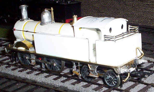
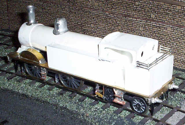
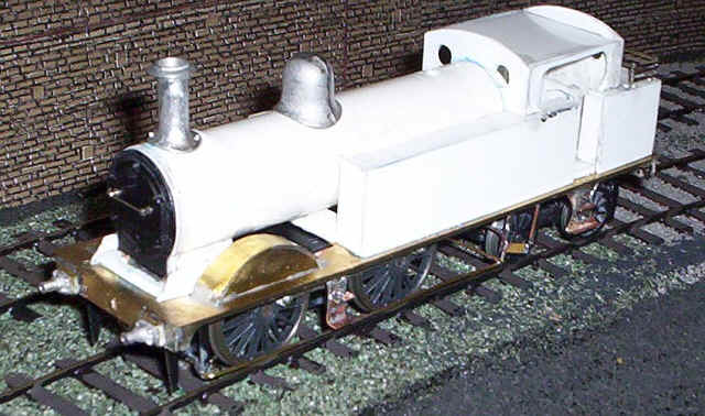
The loco before painting started
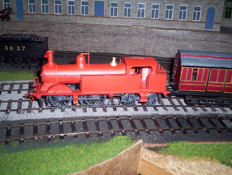
At last we can see some of the detail in the photos! To my delight the undercoat paint hasn't revealed any awful problems.
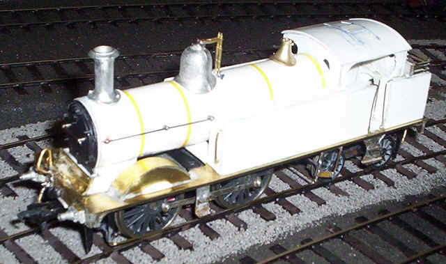
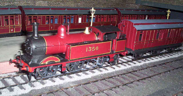
Painting the model in its final colours was somewhat traumatic! The two problems were that my gold marker pen no longer seemed to give quite such a fine line as in the past. However, this was eventually overcome with careful touching up. I decided to omit the lining around the cab opening as I found it too tricky to apply without obtaining a poor result.
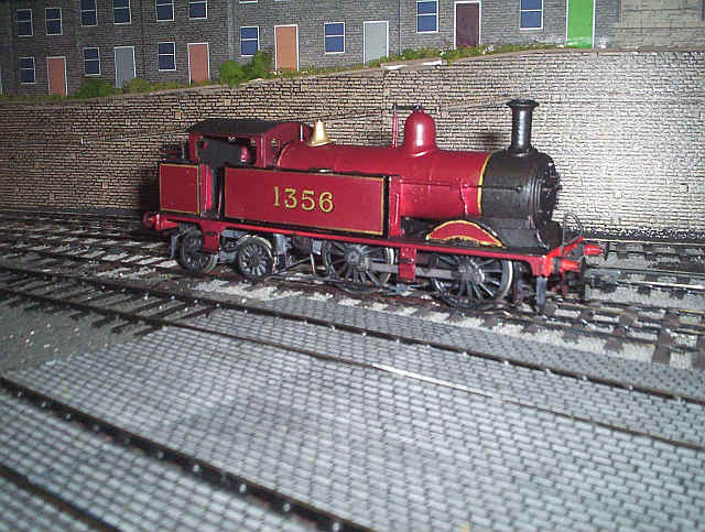
Attaching the number transfers was another story. Using Pressfix transfers it's very difficult to see the precise alignment before you commit yourself. The number I chose, 1356, caused no end of problems and, as is obvious, despite three attempts I have failed to line up the 3 and the 5 correctly. By this stage I'd used up all the threes on my transfer sheet so I'm just going to have to live with this misalignment until I can obtain some Methfix transfers, where you can see the numbers and adjust them.
POSTSCRIPT.
Having obtained another transfer sheet I've now removed the misaligned transfers and replaced them with correct sized (larger) numbers correctly aligned.
Overall despite the various inaccuracies and somewhat poor workmanship in places I'm very pleased with my first attempt at scratchbuilding. Now, the question is what next? - a half cab 0-6-0T would be nice, and they were in unlined black.
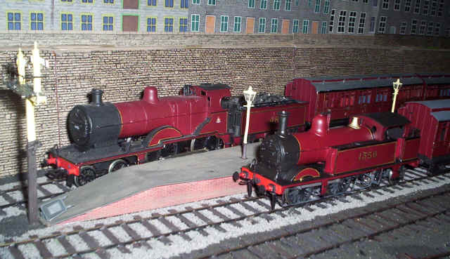
2P and 0-4-4T at Halifax Midland
The second 0-4-4T built in 2024


Most of the construction of the early stages of the second model followed the same methods as for the first except that the motor is by Mashima and the gear box is from Markits. The motor sits much lower than the Portescap one used in the first loco.
The coupling rods were one piece ones from the Gibson 4mm scale range which exactly matched the axle centres of the frames.

Electrical pickup is from the driving wheels and the outer axle of the bogie. The bogie is from a Gibson 4-4-0 kit with a much shorter spacing piece. This is pivoted on a bolt and the axle holes were enlarged slightly. Doing this allows the bogie to pivot but allows the bogie wheels to slide to and fro so that they follow the curvature of the track. It's crude but works and was method recommended me by Alan Gibson. The blocks of plasticard that form the housing for the Bachmann plug in NEM couplings can be seen behind the buffer beams.


Having built most of my recent models with card bodies I have decided to do the same with this model. Here the early stages are seen. Using thick greyboard a base has been glued to the footplate and the side tanks have been fixed to this strengthened with two pieces to cross brace and hold the tank sides vertical. The outer surface of the side tanks have been covered with thin white card.

Construction of the body is almost completely out of card with the exception of the plastic boiler from central heating piping of the correct diameter. The smokebox door is from a spare 4mm scale Airfix 4F 0-6-0 which is pressed into the front of the boiler tube after a little filing. The smokebox saddle is made from shaped layers of card of various thicknesses attached to the brass foorplate with two part epoxy resin. The firebox end of the boiler is attached to the cab front and located using a disc of card cut to the internal diameter of the boiler tube.

The cab front and rear faces are layers of greyboard and card with the windows cut through using a very old hand held metal leather punch. The holes have been slightly opened out using a file. The coal bunker is made from a length of card folded exactly in one piece for the sides and rear. Greyboard is used as reinforcement as for the side tanks.

The chimney, dome and Salter valves and brass safety valve covers have been added - the latter is still loose and will be added after painting. The chimney and dome castings were made by Alan Gibson for S Scale and are therefore different to the ones used on the first version of the 0-4-4T.

The cab roof has been added using a sheet of brass...

..with the coal rails being from nickel silver strip.

The finished model - 1278 was a Bradford Manningham loco in 1922 so is a suitable West Riding loco for Halifax.
Was it better to use card or plastic for the body. Plastic perhaps gives a slightly sharper edge to corners and is a bit more forgiving with minor damage like glue marks. On the other hand card is more or less free and is more environmentally friendly.