Building a Stanier 8F 2-8-0
In July 2019 I decided that the
next S Scale locomotive I was going to build would be a Stanier 8F 2-8-0, using
the etchings and some castings made by Alan Gibson. It isn't the first 8F I've
had as, some years ago, I had a ready built model which Alan Gibson sold
me when I bought all his S Scale stock.
However, for health reason that I
have explained elsewhere on this website I sold this model to an Australian and
of course now regret doing so! I'd had to modify the original locomotive to run
on my layout as described below. Fortunately, I kept the unbuilt 8F kit that I
had so, hopefully, my own model will be as good as the one I sold. The
description of the construction of the new 8F will follow after the text on this
panel.
|
Recently, I was
fortunate to be given a number of completed Alan Gibson LMS and Midland Railway
locomotives. Although nicely built they aren't all suitable for operation on the
sharp curves of Halifax Midland so, in some cases, a partial rebuild will be
necessary.
The first to be tackled was the Stanier 8F,
one of my favourite classes. Perhaps this isn't so surprising as I saw 485 of
the class in my travels around northern England in the 1950s and 1960s.
The model, as originally completed was
powered by a Portescap motor and gearbox and was clearly very powerful.
However, it struggled with the curves on Halifax and also suffered from the
problem of the return crank not being rigidly fixed on the crankpin. This
resulted in the valve gear performing some very strange antics.
Eventually, I decided on a partial rebuild.
Firstly, I constructed a powered tender as described on
this
page. Having proved the concept I decided to remove the motor. This
necessitated dismantling parts of the valve gear, connecting and coupling rods
and removing the rear three axles. The loose connecting rods and return crank
assemblies were temporarily held out of the way, by wrapping some fine wire
around them and securing them at the top of the chassis.
In an attempt to overcome the problem of
rotating return cranks I decided on a somewhat drastic solution. I had used
Romford crankpins for many of my 4mm scale locomotives, and had found them robust
and simple to use. Best of all the return cranks were soldered firmly in place
on the crankpin. I therefore decided to replace the Gibson crankpins with
Romford ones; it was a surprisingly easy task.
The Alan Gibson crankpins were unscrewed
from their holes and these were then opened up a little at a time using fine
tapered broaches. When I judge the holes were just about capable of having the
screw of the Romford crankpin inserted, I gripped the shaft of the pin with
pliers and gently screwed them into the hole. The screw cuts a thread into
the plastic but it's essential that the crankpin is at right angles to the wheel
as you do this. From the effort needed to do this I was pretty certain that they
wouldn't come undone in use. However, I then unscrewed them a few turns and put a drop
of Loctite on the thread and then quickly re- tightened the crankpin.
Once all six of the rear wheels were
converted, it was a relatively simple matter to re-quarter the wheels. I did this
using a mirror behind the model, allowing me to see that the crankpins are set at
90 degrees to each other. The coupling rods (which had all
been hanging loosely from the undisturbed front wheels) and the connecting rods
were then put back on
the crankpins and the chassis test rolled. Once satisfied all was well the little securing washers, that come with Romford crankpins,
were soldered in place. The return crank was then soldered in place in the
correct position.
For once, very little tweaking was necessary
and the free rolling chassis happily rolled around the tightest curve on the
layout - a flange squealing 36" radius. I hasten to add this loco is not
going to be expected to cope with this sort of curvature on a regular basis, but it shows what is
possible.
As the tender is a completely self-contained
unit, all that is needed is a simple loop and hook coupling between locomotive
and tender. The tender seems quite happy picking up current on just four wheels
so, unless matters change, the locomotive itself won't be fitted with pick ups.
The haulage capabilities of the model are
more than sufficient for my purposes as it happily lugs all 30 of my wagons,
most of which are heavy cast metal models, around the layout.
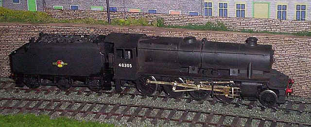
The photo below shows the completed loco.
|
Building the new 8F
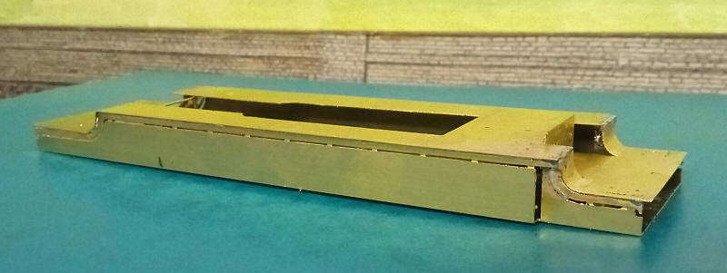
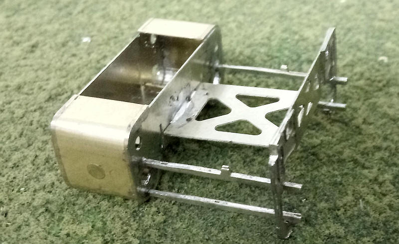
Construction started in the usual way for Alan Gibson kits with the footplate,
running plate and valances assembled on a fold up jig.
As usual I deviated from the suggestion
in the instructions to build the body first and then the chassis. What use is a
model if the running gear doesn't work well?
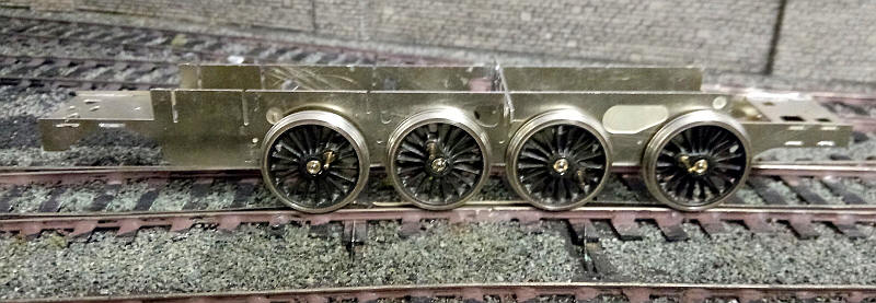
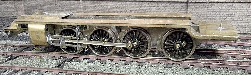
After fitting the bearings to the frames
I've now assembled the main frames using the London Road alignment jigs and
fitted the Markits wheels. Propelling the chassis around the layout revealed no
problems so it's on to the next stage.
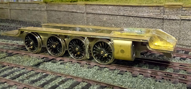
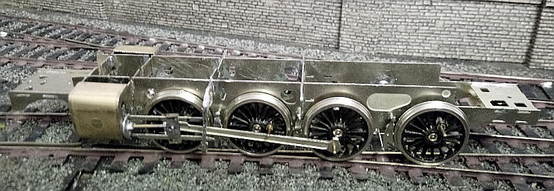
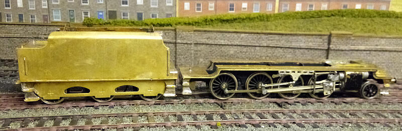
The motion bracket and cylinder assemblies
have been soldered together and slotted in place into the frames but not yet
soldered to the frames.
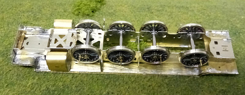
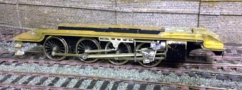
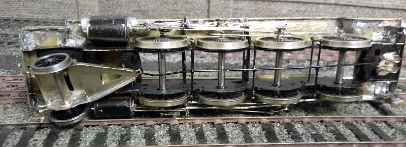
The underside of the chassis shows the
length of brass 'L Profile' that has been soldered to the rear of the front
bufferbeam. This locates the frames with no sideways movement. A 12BA nut and
bolt secures the rear of the chassis to the footplate.
I next assembled the cylinder, motion
bracket and slidebars, all of which went together quite easily.
However, on test fitting these in place it
was obvious that (as I half expected based on previous experiences) there simply
isn't enough clearance between the crankpins on the leading axle and the rear of
the slidebar. This is partly because I'm using Markits wheels which are much
thicker than the thinner Gibson wheels.
As with the Crab and Patriot I will need
to split the cylinder block and motion bracket and reposition them about 1.5 mm
further outboard of the frames.
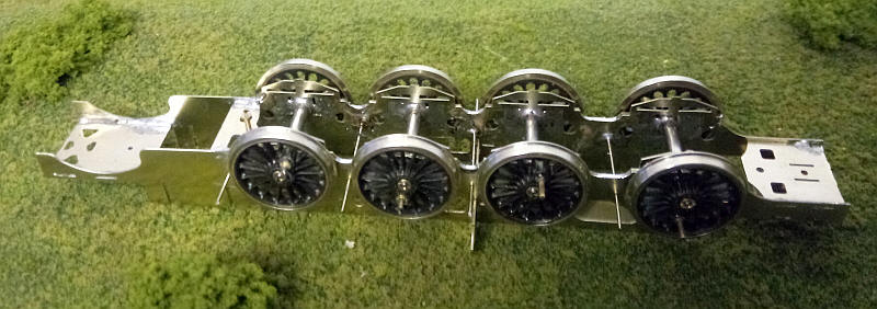
This means that the order of construction
will be slightly different to the instructions. The wheels were all removed and
the etching that carries the springs has been soldered in place together with
the brake hangar wires.
I've repositioned the cylinders and motion
bracket on one side of the locomotive. New slidebars (taken from spares in a
Stanier 2-6-0 kit) have been temporarily fixed in place. These slidebars are a
single layer of nickel silver so give another half a millimetre of clearance.
The crosshead has been fabricated from nickel silver strip as described in the
Patriot, Crab and Class 5 pages. The rear layer of the connecting rod has been
shortened at the crosshead end to so that the rod sits tightly between front and
rear piece of the crosshead.
The footplate was then placed onto the
chassis to ensure that the alterations in the positioning of the cylinders and
motion bracket hadn't affected the way it sits. A few small adjustments were
necessary to do this. Of course, the cylinders now sit slightly further out but
it's a case of accepting this compromise or no 8F.
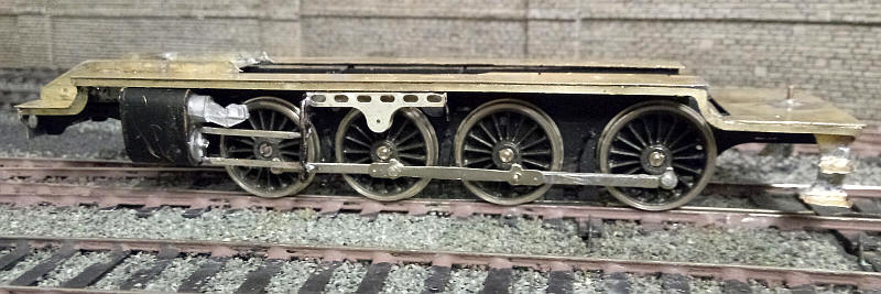
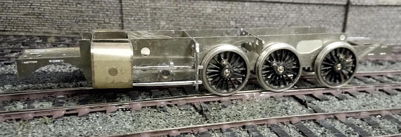
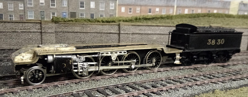
The coupling rods supplied in the kit are
intended to be assembled as on the real 8Fs. The outer rods are pivoted on
extensions to the rods connecting the 2nd and 3rd axles. Doing this successfully
was, for me at least, a step too far so I decided to pivot all the rods on the
crankpins in the normal way. The appearance of the centre rods will stay the
same giving the impression that the outer rods pivot on them. The photo above
shows their appearance.
Of course this meant that I needed two
pairs of coupling rods. The rods between the 1st and 2nd axles come from a
Gibson Somerset and Dorset 2-8-0 kit of which I have several spare frets. The
rear rods were fabricated from some from a spare Crab etching. These were
soldered together like 'Universal' rods with the rear half having the pivot
hole at one end and the front layer having the hole at the other end. Some rod
alignment jigs were passed through the axle holes and their points were pressed
into card mounted on a piece of wood. Two fine panel were tapped into these
positions and hold the two halves of the rods together whilst soldering.
All the crankpin securing washers were
soldered in place except for the one on the third axle were soldered in place/
The connecting rods and return crank go on this axle so in the meantime a piece
of wire insulation holds them in place.
I've also folded up and soldered in place
the expansion link support.
The valve gear on the left hand side is
now complete. To make assembly easier (and without loosing anything in
appearance) the pivot wire on the expansion link support has a short length of
brass tube soldered on it. Once the expansion link has been pivoted on this the
curved front part of the bracket is pressed firmly down on the wire. This locks
the link in place and allows it to move smoothly backwards and forwards without
'flopping about' from side to side. The radius rod should really also go over
this pivot wire but I find it easier to solder it in place to the expansion link
support bracket and motion bracket as this gives a firmer location for the pivot
point with the combination lever at the front of the cylinder.
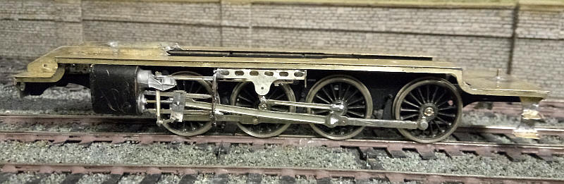
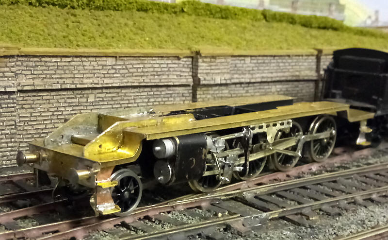
The other side of the 8F's valve gear can
be seen here. There a few changes from the first photo. I found great difficulty
in getting the front face of the crossheads to stay fixed in place so I decided
to rebuild them by making the center piece (which has the piston rod soldered to
it slightly longer and soldering a small piece of 10thou brass wire between the two
pieces of metal. It doesn't look very good but ensures the slidebars work
properly but once painted I doubt this compromise will be obvious.
The second problem was the difficulty of
soldering the return crank to the crankpin on the third axle. In the end I
soldered a crankpin washer on to the crankpin of the third axle (the one used by the connecting rods). Then I gave the crankpin
a drop of oil to prevent unwanted soldered joints. The return crank was then
soldered onto the washer; this solved the problem with the chassis running
smoothly around the 36" radius curves on Pendle Midland.
I've now added the pony truck which is a
simple three piece structure pivoted at the rear and held in place at the front
with a nut and bolt to stop it dropping too far. The wheels are EM gauge profile
from Alan Gibson. I had expected to have to weight the truck but this has not
proved necessary.
Despite the numerous problems the
completed chassis rolls really smoothly and is completely happy on the 36"
radius curves on both Halifax Midland and Pendle Midland. The Midland tender is
being used for running trials as I saw little point in building a Stanier tender
until the loco chassis was built.
The buffers and front steps have been
added. Luckily pony truck wheels don't touch the steps.
The tender is now largely completed so the
chassis has been given a good test running session to iron out some minor
problems.
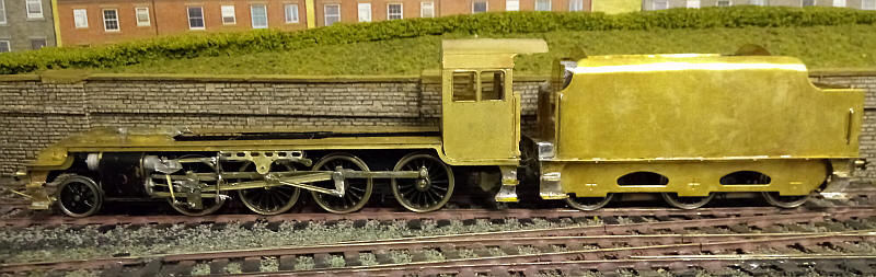
The cab is now in place.
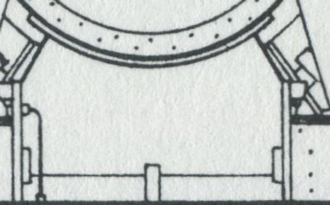
Included with the kit was a Belpaire
boiler casting which was intended for a Class 5. In order to modify it to
resemble an 8F firebox I extended the lower sides by about 3mm using layers of
thick cardboard glued inside the firebox to support the narrow strips on the
lower edges. A layer of paper was then glued to overlap the joint between card
and metal.
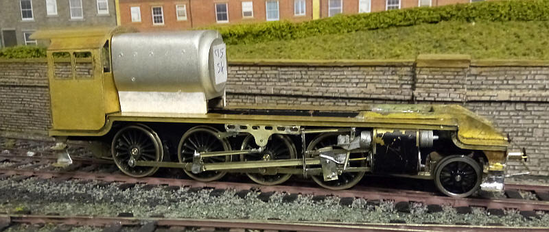
The boiler is being made in the same way
as the Class 5. A length of plastic central heating pipe was split along the
long axis and four coins (this time 20 cent Euro coins!) forced inside and held
in position with epoxy. A narrow strip of tube about 6mm wide was cut and glued
along the bottom of the boiler tube to complete the circle. The cast firebox
door casting was then glued to the front of the boiler/ smokebox tube.
As there was no cast smokebox saddle I cut
a piece of plastic to act as the front support for the boiler and glued this to
the vertical section of the footplate behind the low 'piano' section of the
footplate.
The boiler tube has had a cut made just
behind the smokebox. This cut was made to within about 5mm of the top of the
tube and allows the boiler to be bent slightly so that the top of the firebox
will be level. A few silvers of plasticard were glued into the gap to make a
wedge. The tube and the firebox casting have now been glued together and the
outer card layer of the smokebox has also been glued in place.
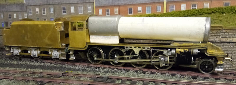
After quite a bit of adjustment I arrived
at the final taper boiler outline. This was built up using the techniques used
for the Class 5 - 5mm wide strips of card were glued to the boiler barrel - two
rings were positioned at the firebox end and one in the middle. Along the top of
the boiler tube a narrow strip of card was glued to give additional support for
the fixing of the dome and top feed. Likewise strips of card were glued along
the bottom of the boiler tube to give the required depth under the boiler. A
length of card was rolled and then glued around these supports with the
underside coated liberally with epoxy. It was held in place with rubber bands
until set. Finally an outer layer of very thin card was secured (again with
epoxy) over both the taper boiler and the smokebox. Finally, all the card was
give a coat of wood hardening fluid.
The brass cab and footplate have been
throughly cleaned and sprayed with primer. The boiler and firebox have been
secured permamently to the metal with epoxy and bolts through the cab front and
under the smokebox.
The smokebox saddle has been fabricated
from plasticard strip whilst the steam pipes are from a length of square section
plastic with the corners filed to the correct shape and then glued ot the
footplate and smokebox. The chimney, top feed and dome are all Gibson white
metal castings.
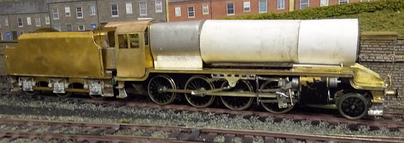
I feel the model is beginning to look like
an 8F at last.
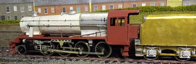
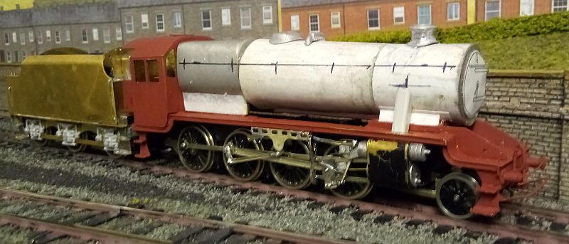
The pipework and handrails have been added
on the left hand side of the locomotive.
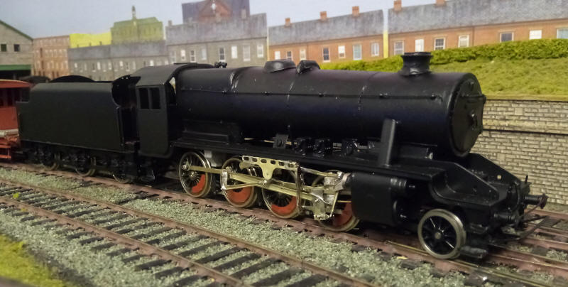
The loco is now basically complete with
just the final painting and transfers to be applied. A few details have been
added since the previous photo: sandbox fillers, lubricators, safety valves and
the widening at the bottom of the firebox. I've also added pickup wires on the
first and third axles which has improved running.
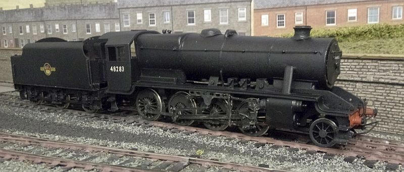
The locomotive is now finished with
glazing and transfers added. 48283 was a Leeds Holbeck engine from 1948 to its
withdrawal in 1967 apart from one month at Southport shed in 1950.
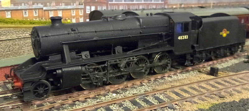
And the other side.